
Replacing a Magnetostrictive Displacement Sensor in a Hydraulic Cylinder: Record Before You Remove
When a magnetostrictive displacement sensor fitted inside a cylinder has to be replaced, the usual routine is: take it out, match a new one to the old, fit it, switch on.
That routine only works if the new unit has exactly the same mechanical datum and electrical zero as the old one — which almost never happens by itself. So the jobs that come back are rarely about technique. They come back because nothing was recorded before removal, and nothing was recalibrated afterwards.
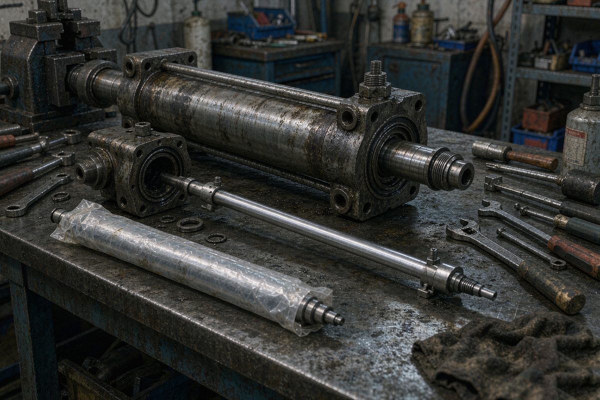
Four confirmations before you touch anything
Release the pressure and isolate. With residual pressure in the cylinder, the head and rod can come out under load. Return the circuit to zero and confirm on the gauge that pressure has actually fallen — closing the pump is not the same as releasing pressure.
Let it cool after release. A cylinder just off shift can sit at seventy or eighty degrees. That is dangerous to work on, and dimensions taken hot will change once it cools.
Have the tools ready. Cylinder heads often need a dedicated wrench or socket, and some have locking features. Improvised tools are the quickest way to damage the flats.
Verify the spare first. Do not discover after removal that the flange form is wrong. The three-layer check — mechanical, electrical, parameter — is in three-layer check when replacing a part. If the original model is discontinued, the route to a substitute is in finding a replacement when the original is discontinued.
Three dimensions and one datum to record before removal
These are gone the moment the unit comes out.
- The length or protrusion of the old unit. Measure from the cylinder head face to the rod end, or how far the rod stands proud of the head. This sets how deep the new rod sits inside the cylinder; get it wrong and the whole travel shifts.
- The magnet position on the piston. Measure the distance from the magnet to the piston face. Move the magnet and the reading band that corresponds to the same stroke changes with it, which changes the scaling.
- Wiring and connector form. Photograph them together with the pin assignment. Wire colours can differ between batches of the same series, so working from colour alone risks reversing supply and signal.
- The original zero datum. Note on the screen what the reading is with the piston fully retracted and fully extended. Those two numbers are the target for calibrating the new unit, and they are more direct than any drawing.
Where possible, save the full-stroke reading curve as well. Overlaying the new curve on the old one after fitting shows immediately whether the shape is right — see spotting early degradation from the position curve.
Which surfaces must not be marked
| Surface | Consequence of damage | How to protect it |
|---|---|---|
| Rod outside diameter | Scores disturb the return signal; severe ones write the unit off | Pad it when withdrawing; never drag it along the floor |
| Cylinder head sealing face | Oil weeps, pressure will not hold, the cylinder goes for repair | Fit new seals every time; never reuse old ones |
| Head bore and thread | Will not seat fully, or seats off-centre | Load the thread evenly; no forcing one side |
| Magnet bore | Uneven clearance produces a cyclical shudder in the reading | Use non-magnetic tools to handle the magnet; avoid knocks to the bore |
Keep the old unit rather than discarding it. It is the best physical reference — checking flange hole spacing and rod length against it with a caliper is faster than working from drawings. It also allows the failure cause to be identified, which matters more than the replacement itself; the method is in three steps to check whether a unit is good or bad.
Reassembly order
Reassembly largely reverses removal, but two points catch people out.
Fit the magnet correctly before the rod goes through. The magnet has to be secured to the piston before the piston enters the bore; once assembled, adjusting it means dismantling again. Magnet fixing and the common traps are in five magnet traps that cause most installation problems.
Tighten the head in stages. Work diagonally in two or three passes rather than once. A single full-torque pass squeezes the seal off-centre, which shows up not immediately but after a period of running, as a weep.
Do not run automatic cycles straight away. Push the piston from one end to the other by hand first — this is the best moment to feel whether the assembly is binding.
Why recalibration matters more than the swap
The new unit will not share the electrical zero and mechanical datum of the old one, so fitting it as-is guarantees an offset. Calibration is part of the job, not an optional extra.
The sequence is: establish the mechanical datum first, then set the range by the two-point method, as described in zero calibration: mechanical datum plus the two-point method. Calibrate after the electronics have reached thermal equilibrium — calibrating cold and running hot is a combination that recurs on the same site.
Two closing steps. Walk the full stroke by hand and confirm the reading is continuous with adequate margin at both ends. Then re-torque the flange and bracket bolts after one shift, because newly fitted fasteners loosen over the first few thermal cycles.
Field notes for engineers
- Photograph the two extreme readings on the screen before dismantling. That is the cheapest possible record of the zero datum, and far more reliable than hunting for design values on a drawing later.
- Replace the head seals whatever they look like. The cost of one seal is trivial next to dismantling the cylinder a second time.
- Keep the old unit and establish whether it died of old age or was killed by something else. If the same machine has taken two units in a row, the thing to investigate is oil cleanliness or mounting condition, not the part.
- Between fitting and power-up, push the full stroke by hand. Problems found by hand at that stage cost far less than the same problems found after wiring and parameters have been set.
- Where the machine runs continuously, file the recorded dimensions and reading datum into the machine history. The next replacement then has something to work from.
Frequently Asked Questions
Q: What has to be recorded before removing the old unit?
Four items: the length or protrusion of the old unit measured from the cylinder head face, the distance from the magnet to the piston face, the pin assignment on the connector, and the two screen readings with the piston fully retracted and fully extended. The first three are gone once the unit is out; the last is the target for calibrating the new one.
Q: If the replacement is the same model, does it still need calibrating?
Yes. The same model means the mechanical interface matches, but every unit has its own electrical zero and factory calibration, so an offset is certain on fitting. Establish the mechanical datum first, then set the range by the two-point method, and do it after the electronics have reached thermal equilibrium.
Q: Is the old unit worth keeping?
It serves two purposes. It is a physical reference — checking flange hole spacing and rod length against it with a caliper is quicker than reading drawings. And it allows the failure cause to be identified, distinguishing end of life from dirty oil or poor mounting. If the same machine has taken two units in a row, the part is not the problem.
Q: What should be done first after reassembly?
Do not start automatic cycles. Push the piston from one end to the other by hand and feel for binding, which is when assembly faults are easiest to catch. Once travel is smooth, power up and check that the reading is continuous, recalibrate range and zero, then re-torque the flange and bracket bolts after one shift.
Related Products

Series 16 Hydraulic Cylinder Built-in
View Product
Series 17 Hydraulic Cylinder Integrated
View Product
Series 19 H-Type Built-in Cylinder
View Product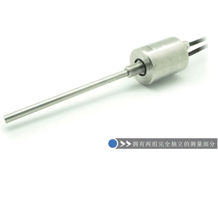
Series 16R Redundant Design Built-in
View ProductRelated Applications

Series 16 Hydraulic Rod Magnetostrictive Displacement Sensor Application Cases
View Details
Series 17 Hydraulic Cylinder Integrated Magnetostrictive Displacement Sensor Application Cases
View Details
Series 19H Cylinder-Integrated Process Displacement Sensor Application Cases
View Details