
Where to Mount a Magnetostrictive Displacement Sensor: The Wrong Position Moves Both Stroke and Accuracy
Mounting position for a magnetostrictive displacement sensor is often decided on the spot: whichever spot has room. The mismatch only shows up during commissioning, when the reading does not agree with the process.
Breaking the reading down makes it obvious. It is always the distance between the fixed end of the rod and the magnet. Whatever the fixed end is bolted to becomes the datum, and whatever carries the magnet is what gets measured. Choosing a position is choosing a datum.
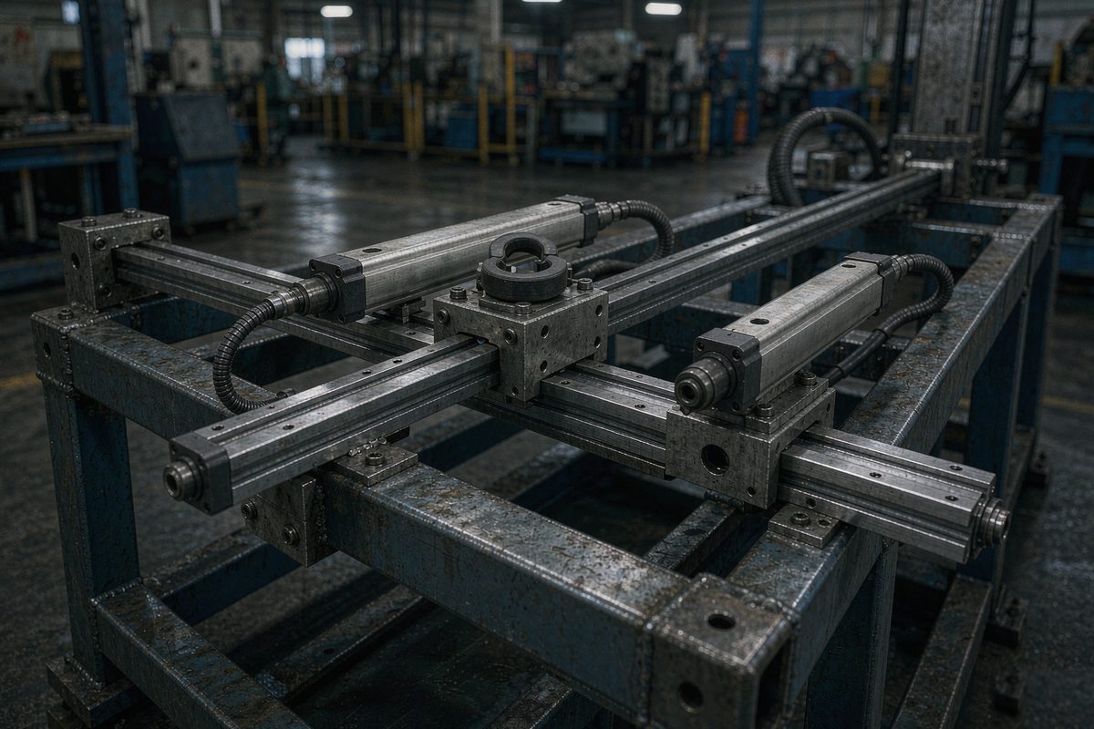
Decide which two points you are measuring between
Before choosing a position, answer one question: in process terms, this displacement runs from where to where?
Take a hydraulic press. If the process cares how far the ram has travelled relative to the table, the datum belongs on the table side, with the magnet carried by the moving part. If the process cares about piston travel relative to the cylinder body, the datum belongs on the body. The two statements sound similar and produce completely different mounting positions.
On welding, bending and shearing equipment, the process usually cares about workpiece position relative to the tool. The datum follows the workpiece locating face, not the frame.
Get this wrong and no amount of careful fitting helps — the reading will track the thermal and load-induced distortion of the frame for the rest of its life.
Three mounting patterns and what each measures
| Pattern | What it measures | Where it suits | What to watch |
|---|---|---|---|
| Fixed end on the frame, magnet on the moving part | Travel of the moving part relative to the frame | Most machine tools, presses, gates | Frame distortion from heat and load enters the reading |
| Fixed end on the moving part, magnet on the frame | Frame relative to the moving part, in reverse | Cramped moving parts where only the frame side has room | Cable has to travel with the moving part; leave a service loop |
| Both ends on moving parts | Relative displacement between the two moving parts | Synchronising mechanisms, twin cylinders, clamps | Brackets must pass only axial motion, absorbing each side separately |
The third pattern is the one that goes wrong most often. Both motions have to be transmitted through the brackets, and if those brackets also pass radial movement, the reading picks up something that should never have been in it. The bracket rules are the same as for external mounting: rigidity, parallelism and slider float.
Three checks once the position is fixed
- Stroke coverage. The usable range has to cover the full travel of the moving part with margin at both ends. One point catches people out: nominal range is not usable length, because each end has a dead zone that cannot be read. The figures are in the dead zones at each end of the usable range.
- Mechanical stops. Confirm that with the moving part against its hard stop, the magnet is still inside the usable range. Some machines stop on the cylinder itself and some on an external block, and the magnet limit position differs between them.
- Serviceability. Once fitted, can the rod be withdrawn? Is there room for a hand at the junction box? Does changing one require dismantling a pipe run first? These questions belong on the drawing, not on the day of fitting.
The further from the axis of motion, the more the error is amplified
This is the least visible and most expensive item in position selection.
Ideally the measuring axis coincides with the axis of motion being measured. In practice there is always an offset — the rod sits 200 mm above the table, say, while the motion axis runs below it. In that case any angular tilt of the moving part turns into a displacement error in the reading: the tilt angle multiplied by the distance between the two lines.
The arithmetic makes the difference plain. At 50 mm offset, 0.1 degrees produces about 0.087 mm of error. At 500 mm offset, the same 0.1 degrees produces 0.87 mm — ten times as much. And 0.1 degrees is small: rail wear and load deflection are both capable of producing it.
So there is a clear order of preference: stay close to the axis of motion if you can. Where that is impossible, either stiffen the structure against angular movement or budget the error into the machine accuracy. Do not expect calibration to absorb it — calibration moves the zero, not an error that varies with position.
Choose the mounting type after the position, not before
The order matters. Position is decided by the process; mounting type is decided by selection.
Inside the cylinder it is a built-in arrangement, which means drilling the piston rod, and the three dimensions to settle before drilling are in three things not to get wrong before a built-in hole is drilled. Outside the cylinder it is an external or rail arrangement, and bracket rules are in how to build an external mounting bracket that stays put. Installation steps and parameter settings for both are in built-in and external: how to install and commission.
Position and stroke come first, then the mounting space is verified. That sequence runs through stroke, mounting, environment and output in four steps, and it does not improve by being reversed.
Field notes for engineers
- Once the position is agreed, draw one line on the drawing from the process datum point to the fixed end of the rod and measure it. The length of that line is the segment that every thermal cycle will move.
- Where both ends are on moving parts, loosen both brackets during assembly and let the rod find its own centre before tightening either. Tighten one first and assembly stress stays in the rod.
- On installations with a large offset from the axis of motion, apply a small side load deliberately after fitting and watch how far the reading moves. A visible change means the amplification effect is already in the system.
- Retrofit projects rarely offer a choice of position. When there is none, shorten the distance from rod to motion axis rather than tidying the layout by moving the rod further out.
Frequently Asked Questions
Q: How much difference does frame mounting versus carriage mounting make?
The difference is the frame distortion itself. With the fixed end on the frame, thermal growth and load deflection of the frame both enter the reading. With the fixed end travelling on the carriage, that contribution is excluded. The hotter and more heavily loaded the machine, the more visible the difference — and which one to use depends on whether the process measures relative to the frame or relative to the workpiece.
Q: Does the offset from the axis of motion really affect accuracy?
Yes, and it is amplified by the offset distance. Any slight angular tilt of the moving part adds an error equal to the tilt angle multiplied by the distance between the two axes. At 50 mm the effect of 0.1 degrees is about 0.087 mm; at 500 mm the same tilt gives 0.87 mm. Rail wear and load deflection can both produce 0.1 degrees.
Q: What should be watched when both ends are on moving parts?
Above all, the brackets must not pass motion that should not be measured. With both ends moving, each bracket has to absorb its own radial play and any lack of synchronisation, passing only axial displacement. During assembly, loosen both brackets, let the rod centre itself, then tighten in turn so no assembly stress is left in the rod.
Q: The position is fixed but the stroke does not fit. Can range be adjusted?
It cannot. Usable range is set by the physical length of the rod, and the dead zones at each end are fixed and cannot be recovered. If the stroke genuinely exceeds the range, the only options are a longer specification or a mounting position that covers the stroke better. Forcing an undersized unit into service drives the magnet into the dead zone and the reading is simply lost.
Related Products




Related Applications

Multi-Industry Application Cases for Magnetostrictive Displacement Sensors
View Details
Series 16 Hydraulic Rod Magnetostrictive Displacement Sensor Application Cases
View Details
Series 18 Profile Magnetostrictive Displacement Sensor Application Cases
View Details