Dead Zones at Both Ends: Why a Magnetostrictive Displacement Sensor Must Not Bottom Out
At both ends of a magnetostrictive displacement sensor's effective measuring range there is a region that cannot be measured accurately, called the measuring dead zone (blind zone). The dead zone is set by the electronics-head mounting end and the physical size of the position magnet; it is structurally inherent and cannot be eliminated. When specifying, the dead zones must be subtracted from the nominal measuring range, or you get the typical mismatch of "nominal range is enough, but the ends of the stroke cannot be read".
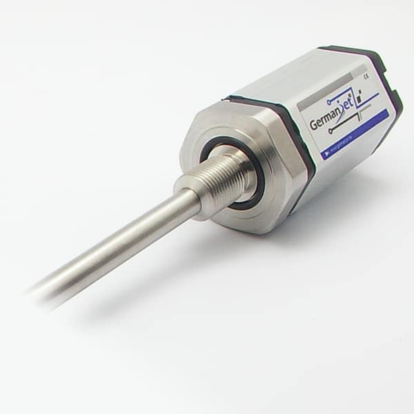
Where the dead zones come from
- Electronics-head-end dead zone: there is a fixed distance from the point where the current pulse is launched to the echo-detection circuit; over a short stretch near the fixed end the echo and the launch edge cannot be distinguished;
- Free-end dead zone: the magnet itself has axial length; when it travels near the free end of the rod, the echo and the end reflection superimpose and the signal is distorted.
How dead zones relate to effective measuring range
Nominal measuring range is the rod's effective measurable interval, equal to the overall mechanical length minus the dead zones at both ends. Stable readings exist only inside the effective range. Dead zones are not a generic “about 30 mm at each end” estimate — take the catalogue figures for that series, and check hole depth and mechanical limits against that model’s installation drawing.
Dead-zone figures by series
| Series | Electronics-head / null zone | Rod-end / dead zone | Notes |
|---|---|---|---|
| Series 16 | Per the flat-housing installation drawing | Rod-end blind zone about 63.5 mm | Cylinder cap Ø18G7, rod Ø10 |
| Series 17 | Null zone 50 mm | Dead zone 60 mm | Cylinder cap M18×1.5 |
| 19F flexible | Front dead zone 50 mm (stroke <8000 mm) / 130 mm (stroke >8000 mm) | Per the flexible-tube routing drawing | Minimum stroke 250 mm |
| 12 / 18 external | Follow the external-type installation drawing; do not reuse in-cylinder figures | Not pressure-containing | |
On short strokes the dead zones are a larger fraction of length, so it is easier to drive the mechanical stroke into the invalid region. For 19F the overall-length tolerance is +8 mm (stroke <8000 mm) or +15/−5 mm (stroke >8000 mm); that tolerance does not change the measuring stroke.
Engineering notes
- Mechanical zero must fall in the effective zone: at installation, put the machine mechanical zero in the mid-portion of the effective range; do not run into the dead zone;
- Stroke calculation includes dead zones: using the method in selection calculations in practice, check stroke against effective range, not nominal length;
- Leave margin in in-cylinder drilling: cylinder bore depth must cover the mechanical length; see in-cylinder drilling and machining requirements.
The measuring principle is in the magnetostrictive effect and the Wiedemann effect; overall installation and commissioning points are in installation in practice; multi-magnet layout is also constrained by dead zones — see multi-magnet measurement.
Practical tips for engineers
- 19F front dead zone: 50 mm when stroke <8000 mm, 130 mm when stroke >8000 mm; always subtract this when calculating effective stroke.
- Total sensor length tolerance: +8 mm when stroke <8000 mm, +15/-5 mm when stroke >8000 mm; this tolerance does not affect the measuring stroke.
- 19F minimum stroke 250 mm; for shorter strokes choose another series.
Frequently Asked Questions
Q: Can the dead zones be eliminated?
No. They are structurally inherent, caused by the electronics-head end and the size of the magnet, and can only be subtracted from the measuring range.
Q: Does nominal measuring range equal measurable length?
No. Effective measuring range equals overall mechanical length minus the dead zones at both ends. Series 16 rod-end blind zone is about 63.5 mm; Series 17 is 50 mm null zone / 60 mm dead zone; 19F front dead zone is 50 mm or 130 mm by stroke. Do not estimate about 30 mm at each end.
Q: What happens if the magnet enters a dead zone?
The reading becomes unstable or goes out of range; that is normal behaviour, not a sensor fault.
Q: Can dead zones be estimated as about 30 mm at each end?
No. That was an illustrative figure and does not match . In-cylinder: Series 16 rod-end about 63.5 mm; Series 17 null zone 50 mm and dead zone 60 mm; 19F front dead zone 50 mm (stroke below 8000 mm) or 130 mm (above 8000 mm). Hole depth and mechanical limits must be calculated from that model’s installation drawing.
Related Products

Series 19 H-Type Built-in Cylinder
View Product
Series 17 Hydraulic Cylinder Integrated
View Product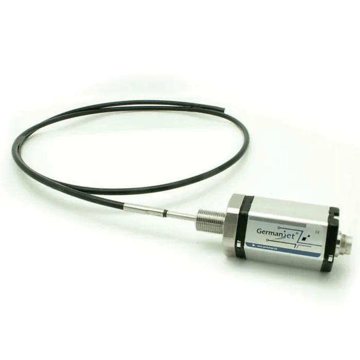
Series 19F Flexible Long-stroke
View Product
Series 12 General-Purpose
View ProductRelated Applications

Multi-Industry Application Cases for Magnetostrictive Displacement Sensors
View Details
Series 17 Hydraulic Cylinder Integrated Magnetostrictive Displacement Sensor Application Cases
View Details
Series 19H Cylinder-Integrated Process Displacement Sensor Application Cases
View Details