
Magnetostrictive Displacement Sensor Series 197: EtherCAT State Machine and DC Clocks
Series 197 is Germanjet’s EtherCAT fieldbus magnetostrictive displacement sensor. The core EtherCAT mechanism is “processing-frame on-the-fly” — the Ethernet frame issued by the master flows through each slave in turn, and the slave reads and writes its own data segment at the instant the frame passes, without buffering the whole frame and then forwarding. That yields the strongest real-time performance and the shortest scan cycle among industrial buses; with DC distributed clocks, high-accuracy synchronisation between slaves is possible. Series 197 is therefore used mainly for high-speed multi-axis synchronised control, such as servo-hydraulic pressing, multi-cylinder synchronised lifting and high-speed reciprocating mechanisms.
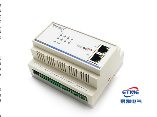
Why EtherCAT is fast
A conventional Ethernet bus sends a separate frame to each slave; more nodes mean more frames and the cycle lengthens linearly. EtherCAT puts all slaves’ data in one frame; slaves use a dedicated communication chip to “fly-read and fly-write” at hardware level, with nanosecond-scale delay. The result is:
- Cycle time is set essentially by the total amount of data, not by node count;
- Message utilisation is high; one frame can carry a large volume of process data;
- No switch is needed; the slave itself has forwarding capability.
For a displacement sensor this means denser position sampling in high-speed motion and “fresher” data at the controller. But note: a fast bus does not mean a fast sensor. The sensor update rate is set by the measuring principle — magnetostriction must wait for the torsion wave to travel from the magnet ring back to the electronics head; the longer the measuring range, the longer the wait. Typical update rate is about 0.5 ms (shorter ranges) to 5 ms (very long ranges), depending on measuring range. If the bus cycle is set to 1 ms and the sensor update rate is 3 ms, the master will read repeated values in succession. How to match response time to the control cycle is in How to match response time / refresh rate to the control cycle.
Slave configuration: ESI file and state machine
An EtherCAT slave describes its capabilities to the master through an ESI (EtherCAT Slave Information, XML format) file: supported sync managers, PDO mapping, object dictionary, DC support. The configuration flow is usually: import ESI → scan the bus → the master auto-matches slaves → configure PDO mapping and cycle → start.
Slave running follows a state machine: Init → Pre-Operational → Safe-Operational → Operational. The key diagnostic in commissioning is “which level it is stuck at”:
| Stuck state | Common cause | Where to look |
|---|---|---|
| Stuck in Init | ESI mismatch, slave not identified | Check ESI version against device model; check cable and port order |
| Stuck in Pre-Op | PDO mapping wrong, mailbox communication abnormal | Check that mapped objects and data length match reality |
| Stuck in Safe-Op | Cyclic data not arriving on time, DC synchronisation not established | Check cycle-time setting, DC configuration, slave order |
| Repeatedly dropping out of Op | Working counter (WKC) abnormal, lost frames | Check cable quality, connectors, topology and interference |
The full ESI and DC configuration steps are in EtherCAT slave configuration: XML and distributed clocks.
DC distributed clocks: the essence of synchronisation
DC (Distributed Clocks) solves “several slaves acting / sampling at the same instant”. The mechanism is to take one slave’s local clock as the reference clock; the master measures each slave’s propagation delay and periodically sends offset and drift compensation so that clocks across the network align.
For displacement measurement the meaning is: position sample instants of the axes in a multi-axis system can be aligned. Without synchronisation, axes sample at different instants within the cycle; in high-speed motion the data of different axes represent different moments, and the deviation the synchronisation algorithm then calculates already contains error.
A boundary to note: DC aligns the sample-trigger instant; it cannot remove the sensor’s own measuring delay. The physical time from trigger to result still exists and varies with measuring range, so a multi-axis synchronised system should as far as possible use sensors of the same measuring range — a large range difference means different measuring delays on each axis, and synchronisation accuracy is compromised. Deeper analysis of DC synchronisation and jitter is in EtherCAT real-time performance explained.
Topology and cabling
An EtherCAT slave has IN and OUT ports and must be strung in order: master → slave 1 IN, slave 1 OUT → slave 2 IN, and so on. Reversing the connection causes the slave not to be identified or the order to be wrong. EtherCAT does not need a terminating resistor; leave the last slave’s OUT open (the frame turns around there).
Cabling requirements match industrial Ethernet: use industrial-grade shielded network cable, avoid long parallel runs with power cables, and lock connectors fully. A frequent field issue is intermittent lost frames from oxidised or unlocked connectors, appearing as the slave occasionally dropping out of Op. Systematic investigation of bus interference is in Fieldbus interference: earthing, shielding, topology.
Where Series 197 sits against other interfaces
| Dimension | EtherCAT (197) | CANopen (194) | PROFINET (199PROFINET) | SSI (192) |
|---|---|---|---|---|
| Real-time performance | Strongest; cycle can be made very short | Medium | Strong (IRT mode) | Point-to-point, instant determined |
| Synchronisation | DC distributed clocks | SYNC message | IRT isochronous synchronisation | Set by the master’s trigger instant |
| Multi-axis expansion | Excellent; string in series | Excellent; shared bus | Excellent | Poor; independent wiring per axis |
| Configuration file | ESI (XML) | EDS | GSDML | None; three parameters |
| Terminating resistor | Not required | 120 Ω at each end | Not required | Not required |
| Typical application | Servo hydraulics, high-speed multi-axis synchronisation | Mobile machinery, cost-sensitive multi-axis | New Siemens-system lines | Single-axis digital reading |
If site wiring space is tight and the number of connectors should be reduced further, consider the single-M12 Series 198; see Series 198 single-M12 EtherCAT explained. The overall trade-off among the four fieldbuses is in Comparing the whole fieldbus range. Product pages: Series 197 EtherCAT, Series 194 CANopen. General fieldbus wiring points are in Fieldbus practical guide; sensor configuration for multi-axis synchronisation is in Selecting for multi-axis synchronisation.
Practical tips for engineers
- The Series 19 analog programming tool can set the zero and end values anywhere within the nominal factory stroke range.
- The Series 19 Profibus simulator can check sensor functions, read magnet-ring positions and diagnostic data, and change the slave address.
Frequently Asked Questions
Q: Why is EtherCAT faster than a conventional fieldbus?
EtherCAT puts all slaves’ data in the same frame. Slaves use a dedicated communication chip to read and write their own data segment as the frame passes, without buffering the whole frame and then forwarding, with nanosecond-scale delay. Cycle time is set mainly by the total amount of data rather than node count, and slaves have their own forwarding capability, so no switch is needed.
Q: Does using EtherCAT necessarily make position refresh faster?
Not necessarily. A fast bus does not mean a fast sensor. Magnetostriction must wait for the torsion wave to travel from the magnet ring back to the electronics head; the longer the measuring range, the longer it takes. Typical update rate is about 0.5 ms to 5 ms, depending on measuring range. If the bus cycle is set shorter than the sensor update rate, the master will only read repeated values in succession.
Q: How should an EtherCAT slave stuck in a given state be investigated?
Locate the problem class by state: stuck in Init is usually ESI mismatch or a link problem; stuck in Pre-Op is usually PDO mapping or data-length error; stuck in Safe-Op is usually cycle-time setting or DC synchronisation not established; repeatedly dropping out of Op, look first at the physical layer — cable quality, connector lock, parallel runs with power cables.
Q: Can DC distributed clocks remove the sensor’s measuring delay?
No. DC aligns the sample-trigger instant of the slaves. The physical time from trigger to result still exists and varies with measuring range. A multi-axis synchronised system should therefore as far as possible use sensors of the same measuring range; DC cannot recover measuring-delay differences caused by range differences.
Related Products



Related Applications

Series 19D Split-Type Process Displacement Sensor Application Cases
View Details
Series 19F Flexible Process Displacement Sensor Application Cases
View Details
Series 19H Cylinder-Integrated Process Displacement Sensor Application Cases
View Details