
Two Feedback Loops, Not One: Why Spool Position and Cylinder Position Are Measured Separately
A servo valve is fitted and a magnetostrictive displacement sensor is fitted, yet positioning is still poor, or the axis oscillates the moment it is pushed faster. These two complaints usually trace back to one place: spool position and cylinder position treated as the same quantity.
A valve controlled cylinder circuit carries two position values. Where the spool sits is the valve's own business; where the cylinder finally stops is the business of the whole system. Two feedback loops, each covering one half.
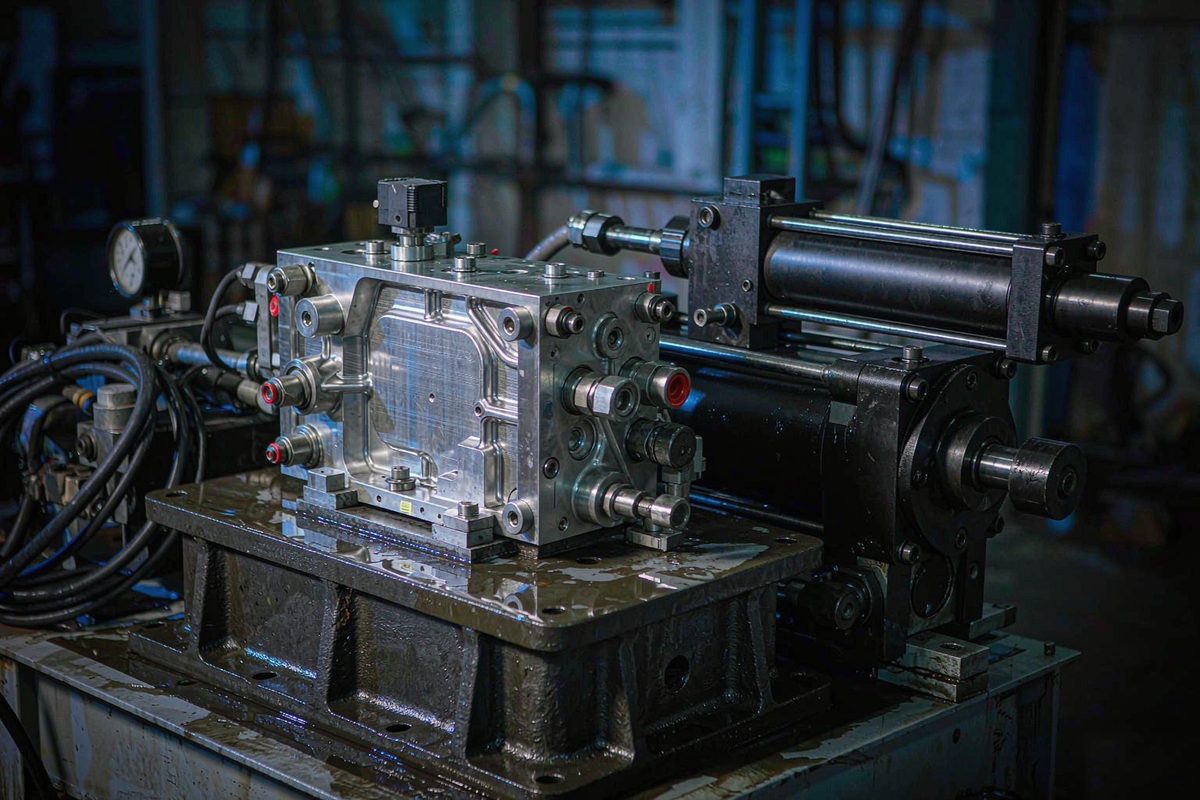
Two Positions in One Circuit, Not One
Servo valves and proportional valves with feedback normally carry an internal displacement element that reads the spool position relative to the body. It compares the commanded opening with the actual opening and closes a small loop entirely inside the valve.
Cylinder position is a different matter. It is where the load actually sits, measured by a magnetostrictive displacement sensor mounted on the cylinder or the frame and sent back to the controller, which then corrects the signal going to the valve.
One value lives inside the valve, the other on the cylinder, with hydraulic oil, pipework and load in between. A correct spool position does not mean a correct cylinder position. Everything that follows comes from that sentence.
The Spool Loop Sets Response Speed
The feedback built into the valve holds the spool opening quickly and accurately. With it, the spool follows the command with little lag and little hysteresis, and is less affected by oil viscosity or pressure fluctuation.
On site this shows up as a clean reversal on a step command, where a valve without feedback drags. On fast reciprocating duty the difference is immediate — it sets how much bandwidth the circuit can reach.
One caution: this feedback watches the spool, not the load. It has no way of knowing what is happening at the cylinder.
The Cylinder Loop Sets Where the Load Stops
An externally mounted magnetostrictive displacement sensor reads the absolute position of the load, which is the quantity the process actually cares about.
Why measure it separately? Because a whole list of things between valve and cylinder never appears in the valve view: load variation, oil compressibility, internal leakage in cylinder and valve, viscosity change with oil temperature, and elastic deformation of cylinder and frame. All of them make the spool opening and the cylinder travel disagree.
These deviations behave like the open loop errors described in why a flow divider cannot align two cylinders. No amount of parameter tuning removes them; only bringing position into the loop does.
With the Inner Loop Only, Positioning Stalls
The spool can be controlled perfectly and the load still fail to arrive. Three typical symptoms: accurate at no load, off as soon as the mould comes on or pressure builds; accurate cold, off once the machine is warm; and different batches drifting in different directions.
The cause is that all of this happens after the spool. The valve believes it opened as commanded while the flow has already been altered by load and oil temperature. Without a cylinder position line, the controller has no idea how far the result is out.
It also explains why adding compensation curves at the valve often fails: the compensation acts on the valve input while the deviation is in the load output.
With the Outer Loop Only, Response Stalls
Conversely, relying on cylinder position alone and expecting the controller to fix everything through the outer loop runs into a ceiling.
Sampling has a period, position update has a period, bus transfer has a period. Added together, that lag limits loop bandwidth directly. If the valve also lacks position feedback, spool dead band, hysteresis and friction all become disturbances the outer loop must handle, and the controller can only buy stability by lowering gain — accuracy survives, speed does not.
The two loops are therefore not alternatives: the inner loop makes the valve decisive, the outer loop makes the machine stop in the right place.
The Division of Labour, Side by Side
| Item | Spool loop (inner) | Cylinder loop (outer) |
|---|---|---|
| What it measures | Spool opening relative to the body | Absolute load position against a datum |
| Who provides it | The valve itself, supplied with the valve | An externally mounted magnetostrictive displacement sensor |
| What it governs | Response speed, hysteresis, stability | Final positioning accuracy and repeatability |
| What it cannot see | Load, oil, internal leakage, oil temperature | Dynamic detail inside the valve |
| What fails without it | Sluggish reversal, limited bandwidth | Drifting position, off as soon as load changes |
The last two rows are the ones most often overlooked. Fitting a servo valve is widely taken to mean the loop is closed — but the valve side was always closed, while the cylinder side is still open. It is the second line that decides machining accuracy.
Four Checks When Selecting the Outer Unit
Injection and clamping on an injection moulding machine are typical places where both loops run at once; the accuracy split between points is set out in mould height and nozzle seat measuring points.
- Update period must keep up with the control period. This is the first figure to work out. A slow unit inside a fast loop feeds the controller a stale position from the previous cycle, and gain brings oscillation. See matching response time and refresh rate to the control cycle.
- Look at repeatability, not resolution. Positioning depends on repeatability, not on how many digits the display shows. High resolution with poor repeatability only amplifies noise once inside the loop. The difference is set out in reading resolution, repeatability and non-linearity.
- The feedback point must sit on the load. Measure the part whose position is actually controlled, not the nearest convenient linkage. Mounting on the valve or on an intermediate rod leaves the load outside the loop again. The full reasoning is in which side it is mounted on changes what is measured.
- Signal form follows loop bandwidth. Analogue has low delay and no protocol overhead, suited to small high bandwidth systems; a bus interface eases multi axis networking and diagnostics at the cost of cycle time and jitter. The trade off is compared in eight interface types side by side.
Three Mistakes Most Often Made on Site
- Mounting the outer unit on the moving side without cable slack. The outer feedback cable flexes with every stroke, so chain radius and fixing points need deciding before assembly. Otherwise the cable fails first and the reading starts jumping.
- Assuming the loop is complete once the valve carries feedback. Valve feedback serves the valve, not the machine. The load position needs its own loop and its own calibration.
- Tuning gain immediately after power up. Closed loop parameters belong after mechanical and hydraulic conditions are stable. Guideway clearance, oil temperature and air in the pipework all have to be settled first, or the gain found on one machine will not transfer to another. The order is described in mechanical datum and the two point method.
Field notes for engineers
- To tell whether a machine has a complete loop, count the feedback cables: one at the valve alone means semi closed loop; a second at the cylinder measuring load position makes it complete.
- Commission in two stages: bring in the outer loop alone with low gain and confirm the position follows but slowly, then raise gain stage by stage. Separating the steps makes it obvious which loop is at fault.
- After fitting the outer unit, run a static check first: park the load at three different positions by hand and compare its reading with a calliper. If static readings disagree, no amount of dynamic tuning will help.
- On long travel outer feedback, avoid routing alongside power cables, particularly for analogue output. The routing checks are described in finding the reflection source first, then shielding and earthing.
Frequently Asked Questions
Q: The servo valve already has position feedback. Is an external unit still needed?
Yes, because the two govern different things. The valve feedback controls spool opening and cannot see load, oil compressibility, internal leakage or oil temperature. Where the load finally stops is measured only by a unit on the cylinder. Without that outer loop nothing corrects the load side.
Q: Can a unit on the cylinder alone replace the spool feedback?
It can work where demands are modest, but there is a ceiling. Sampling, position update and bus transfer lag all limit loop bandwidth, and spool dead band and hysteresis become disturbances for the outer loop, which can only buy stability by lowering gain. Where fast response matters, the inner loop is still needed.
Q: How much faster should the outer unit refresh than the control cycle?
A practical rule is that its update period should be at least on par with the controller position loop period, and clearly slower units do not belong in that loop. Bus cycle and controller scan time also count towards total lag; if any segment exceeds the budget, both synchronisation and stability suffer.
Q: Does it matter which end the outer unit is mounted on?
It does. The feedback point must sit on the part whose position is being controlled. Mounting on the valve or on an intermediate rod leaves the segment between the feedback point and the load outside the loop. Once the position is chosen wrongly, no amount of careful calibration recovers it.
Related Products



Related Applications

Series 17 Hydraulic Cylinder Integrated Magnetostrictive Displacement Sensor Application Cases
View Details
Series 19H Cylinder-Integrated Process Displacement Sensor Application Cases
View Details