
When a Rigid Rod Sags, the 19F Magnetostrictive Displacement Sensor Fits
For hydraulic travel beyond about two metres, the flexible magnetostrictive displacement sensor is the 19F. 19F is the flexible long-stroke model in Germanjet Series 19, using a bendable flexible sensing rod in place of a rigid metal tube. It solves three physical bottlenecks of a rigid rod on a very long stroke: sag under self-weight, feasibility of transport and installation, and the installation path having to be strictly straight. Where the stroke reaches several metres or more, or the installation path cannot guarantee continuous rigid support, a flexible scheme is often the first option that can actually be installed. The measuring principle and accuracy system match the rest of the range — absolute position output, resolution steps 1–100 μm, repeatability of the order of ±0.002 mm.
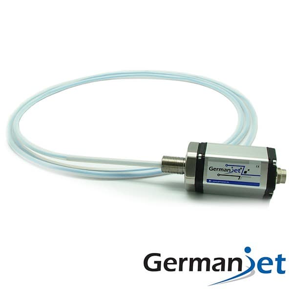
Three bottlenecks a rigid rod poses for a magnetostrictive displacement sensor on a long stroke
First, sag under self-weight. On a magnetostrictive displacement sensor, a slender rod supported as a cantilever or at both ends sags under its own weight; as length increases, deflection grows far faster than linearly. Deflection destroys parallelism between the sensing rod and the magnet-ring motion path, causing reading deviation in mid-stroke that cannot be fully removed by calibration.
Second, transport and on-site installation. A rigid bar several metres long needs special packing; lifting, threading and positioning on site are limited by space. On a retrofit, workshop aisles, existing pipework and machine spacing often cannot let a whole rod through at all.
Third, the path must be strictly straight. A rigid sensing rod on a magnetostrictive displacement sensor requires a straight run throughout, with reliable support. If the measured mechanism’s installation environment has structural obstruction and a detour is needed, a rigid scheme is simply infeasible.
A flexible sensing rod avoids these three points through a bendable materials and structural design: it can be coiled for transport, routed to site conditions, and does not depend on continuous rigid support.
19F versus rigid external options
| Comparison | 19F flexible long-stroke | Rigid external (18 / 19P) | Cylinder-integrated (16 / 17 / 19H) |
|---|---|---|---|
| Stroke suitability | A feasible option for very long strokes | Limited by sag under self-weight | Limited by cylinder stroke and bore depth |
| Sensing-rod form | Flexible, can be bent and coiled | Rigid metal tube | Rigid, inserted into the piston rod |
| Transport and installation | Coiled for transport, easy to position on site | Transported whole; length limited by access | Assembled with the cylinder |
| Path requirement | Can accept a non-straight route | Must be straight throughout with support | Follows the piston-rod bore axis |
| Support need | Fixing points arranged by the routing | Continuous or multi-point rigid support required | Provided by the cylinder body |
| Pressure-containing | No | No | Check peak by series |
| Typical application | Hydraulic gates, rolling mills, large lifts | Ordinary-stroke linear mechanisms | Hydraulic-cylinder position closed loop |
Where a rigid rod cannot be routed or supported, the flexible magnetostrictive displacement sensor is one of the few workable options.
Typical applications
Hydraulic gates and hoist machinery. Gate stroke is large, outdoor installation, long structural span, and the site often cannot provide continuous straight rigid support. Related applications are in Hydraulic gates / hoist machinery: outdoor long-stroke, maintenance-free and Cylinder-stroke monitoring on a hydraulic pumping station.
Metallurgical mills and large presses. Roll-gap adjustment and large hydraulic mechanisms have a long stroke and a complex installation environment; see Roll-gap control on a metallurgical mill: a long-stroke displacement solution.
Large lifting and stacking equipment. Lift stroke reaches several metres; transporting and installing a rigid rod is difficult.
Retrofits constrained by existing structure. When the site cannot accept a whole rigid rod, a flexible scheme is the only path. Selection for retrofit is in Selecting for retrofit of existing plant.
Managing accuracy expectations on a long stroke
On long-stroke selection the accuracy expectation must be calculated first. Non-linearity is a percentage of full scale (% FS). The same 0.02% FS:
- 1000 mm measuring range → absolute error about ±0.2 mm;
- 4000 mm measuring range → absolute error about ±0.8 mm.
This is a mathematical result of the measuring-range base, not a drop in product performance. If the control requirement’s absolute accuracy is tighter than this, consider sectional calibration or a short-range scheme, rather than expecting a long-stroke sensor to deliver short-range absolute error. The relationship of the three accuracy figures is in The three accuracy figures; calibration and linearisation methods are in Factory calibration and linearisation.
Another expectation to manage is update rate: magnetostrictive measurement must wait for the torsion wave to travel from the magnet ring back to the electronics head; the longer the stroke, the longer the wait. Typical update rate is about 0.5 ms (shorter ranges) to 5 ms (very long ranges), depending on measuring range. High-speed reciprocating control must confirm that the update rate meets the control cycle; the method is in How to match response time / refresh rate to the control cycle. The overall long-stroke selection framework is in Selecting for long stroke (2 m and above).
Routing and fixing points
Flexible does not mean it can be bent at will. Actual routing has three constraints:
First, bend radius has a lower limit. Below the minimum bend radius the internal structure is damaged, and measurement may be affected. Routing-path design should leave a generous radiused transition to specification; right-angle bends are forbidden.
Second, fixing points must be arranged reasonably. A flexible sensing rod needs fixing points along the path to prevent shake in operation. Fixings must not clamp the rod too tightly, nor leave an over-long free span.
Third, the magnet-ring path must still be locally parallel to the sensing rod. Flexibility solves the overall path problem; the section where the magnet ring sits must still be coaxial with the rod and non-contacting. This is often misunderstood as “once it is flexible, alignment can be ignored”. Magnet-ring mounting points are in Selecting and installing the magnet ring and Five magnet-ring installation pitfalls.
In addition, measuring dead zones still exist at both ends of stroke; mechanical limits should act before the magnet ring enters the invalid region; see Dead zones at both ends of the measuring range.
Guide-tube dimensions
The 19F flexible rod must be routed inside a non-ferromagnetic guide tube (copper, stainless steel or non-metallic). The jacketed rod runs in a non-ferromagnetic guide pipe for its whole routed length; never substitute a steel conduit. A ferromagnetic tube shunts the magnetic field and appears as a missing magnet or drifting readings. Flange bore and tube size correspond one-to-one; do not mix them:
| Flange | Guide-tube OD | Guide-tube ID |
|---|---|---|
| 10 mm ID flange | < 10 mm | > 8 mm |
| 12.7 mm ID flange | < 12.7 mm | > 8.5 mm |
- Guide-tube length: stroke <8000 mm → stroke + 150 mm; stroke >8000 mm → stroke + 230 mm;
- Front dead zone: 50 mm (stroke <8000 mm) or 130 mm (stroke >8000 mm) — subtract from effective stroke;
- Minimum stroke 250 mm; shorter strokes belong on another series.
Interfaces and neighbouring options
Long-stroke equipment is often multi-axis or distributed; a fieldbus interface can reduce the harness significantly: CAN systems choose Series 194 CANopen; Siemens systems choose 199PROFINET. The interface selection framework is in Analog vs. digital across the whole range.
If the stroke is within a reasonable range for a rigid sensing rod, prefer Series 18 or 19P (see 19P explained) — a rigid scheme is simpler to install and lower in cost. See the 19F flexible long-stroke product page; horizontal comparison of the whole external range is in Comparing the whole external range.
Practical tips for engineers
- Series 19F flexible types must be supported inside a straight or bent guide tube of non-ferrous material.
- With a 10 mm ID flange: guide-tube OD must be <10 mm, ID >8 mm; with a 12.7 mm ID flange: OD <12.7 mm, ID >8.5 mm.
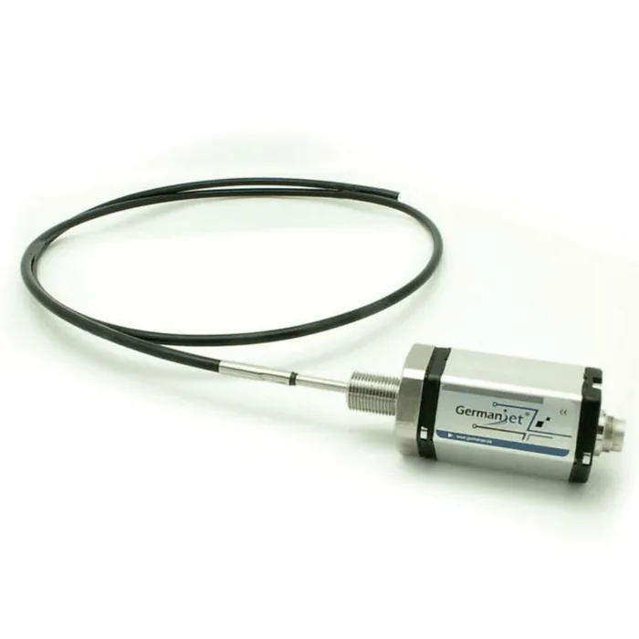
- Guide-tube length: stroke <8000 mm → stroke + 150 mm; stroke >8000 mm → stroke + 230 mm. The flexible-rod sheath is Teflon-coated stainless steel and can be used in heavily contaminated environments.
Frequently Asked Questions
Q: When must a flexible long-stroke displacement sensor be used?
When a rigid sensing rod meets one of three bottlenecks: sag under self-weight destroying parallelism between the rod and the magnet-ring path; transporting and positioning a whole bar limited by access space; or the installation path obstructed by structure so that a straight run with support throughout cannot be guaranteed. When a rigid scheme will do, still prefer rigid: installation is simpler and cost is lower.
Q: How should the absolute error of a long-stroke sensor be estimated?
Non-linearity is a percentage of full scale. The same 0.02% FS is about ±0.2 mm on a 1000 mm measuring range and about ±0.8 mm on a 4000 mm measuring range. This is a mathematical result of the measuring-range base, not a drop in performance. If tighter absolute accuracy is required, consider sectional calibration or a short-range scheme.
Q: Can a flexible sensing rod be bent at will?
No. Bend radius has a lower limit; below the minimum bend radius the internal structure is damaged and measurement may be affected. The routing path must leave a generous radiused transition; right-angle bends are forbidden. Fixing points must also be arranged reasonably along the path, neither clamping the rod nor leaving an over-long free span.
Q: Does a flexible scheme still need magnet-ring alignment?
Yes. Flexibility solves the overall path problem; the section where the magnet ring sits must still be coaxial with the sensing rod and non-contacting. In addition, measuring dead zones still exist at both ends of stroke; mechanical limits should act before the magnet ring enters the invalid region.
Q: How should 19F guide-tube OD and ID be chosen?
Use non-ferromagnetic material. With a 10 mm ID flange: OD <10 mm, ID >8 mm. With a 12.7 mm ID flange: OD <12.7 mm, ID >8.5 mm. Tube length is stroke + 150 mm (below 8000 mm) or + 230 mm (above 8000 mm). Front dead zones are 50 mm and 130 mm respectively.
Related Products



Related Applications

Multi-Industry Application Cases for Magnetostrictive Displacement Sensors
View Details
Series 18 Profile Magnetostrictive Displacement Sensor Application Cases
View Details
Series 19F Flexible Process Displacement Sensor Application Cases
View Details