
Anti-Vibration Mounting Clips for Injection Moulding Sensors: 42.5 mm Hole Pitch, 3.5 kgf·cm Torque, 13 Steps
Both sensors on an injection moulding machine — the one on the clamp and the one on injection — start vibrating the moment the machine moves. The sensor's own vibration rating is one thing; how it is fixed to the machine is another. Neither sensor is bolted directly to the machine panel. There is a pair of anti-vibration mounting clips in between.
Those clips are the cheapest parts in the whole measurement chain, and the easiest to get wrong. Fitted correctly, high-frequency vibration stops at the clip. Fitted badly — a missing washer, torque judged by feel — the vibration travels straight into the sensor core and the reading starts to jitter.
This installation guide was issued by Germanjet in March 2011. Over a decade later the content has barely changed, because two numbers in it have never changed: an installation hole pitch of 42.5 mm and a tightening torque of 3.5 kgf·cm. Below are the 13 steps, plus the two places where site work most often goes wrong.
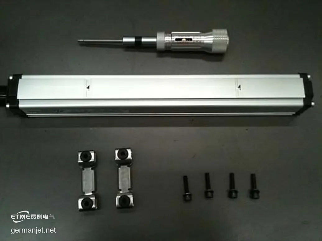
1. What is actually in the pack
Count the parts first — missing parts are the most common cause of rework on site:
| Item | Qty | Function |
|---|---|---|
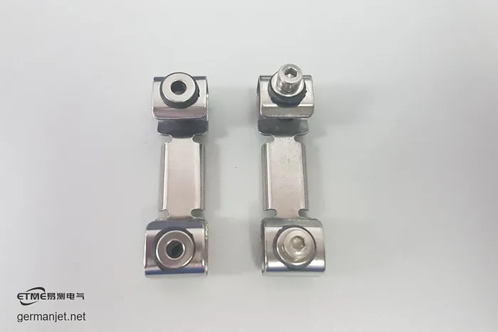
| Anti-vibration mounting clip | 2 | One mounting hole at each end, black elastomer in the middle |
| Washer (shim) | 4 | One per M4 screw, not optional |
| M4 screw | 4 | Two per clip, four in total |
The quantities match up: a pair of clips, two holes per clip, four screws — and four screws means four washers. If a single screw goes in without a washer, or a washer is left in the toolbox, the installation is already incomplete.
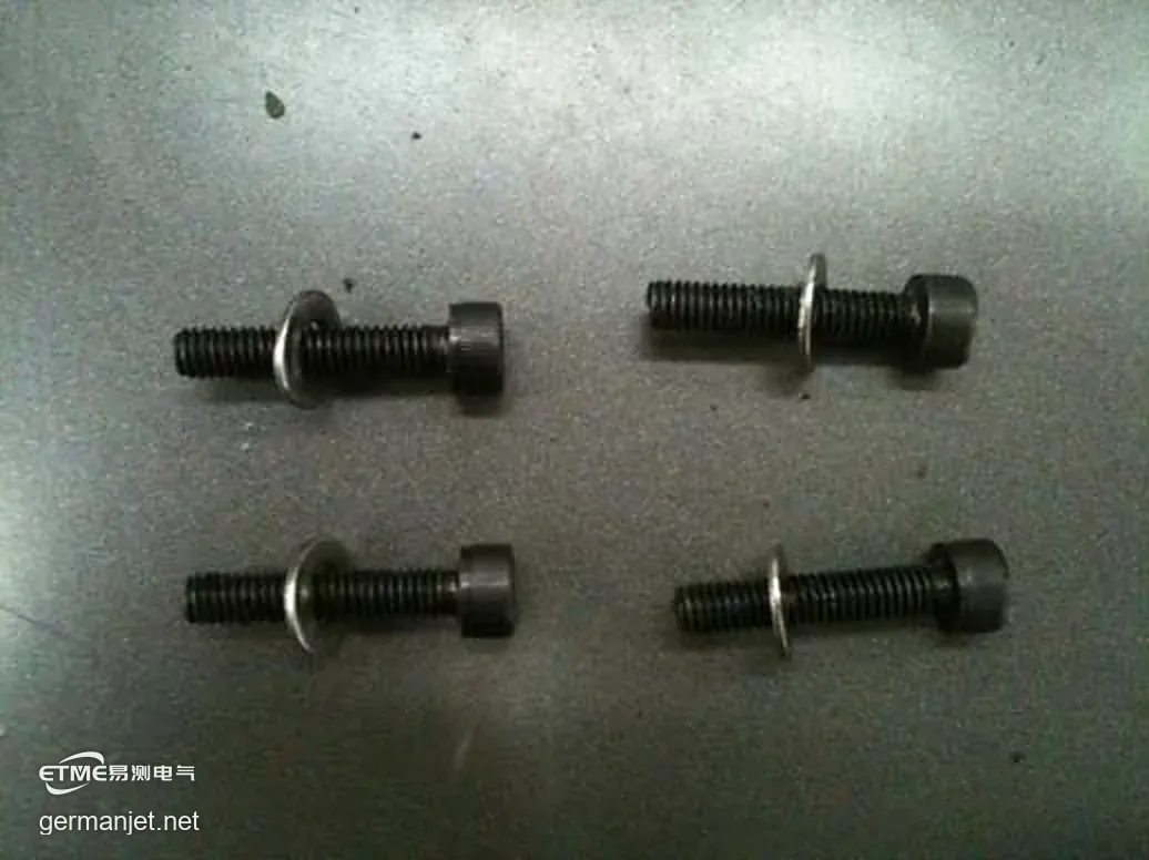
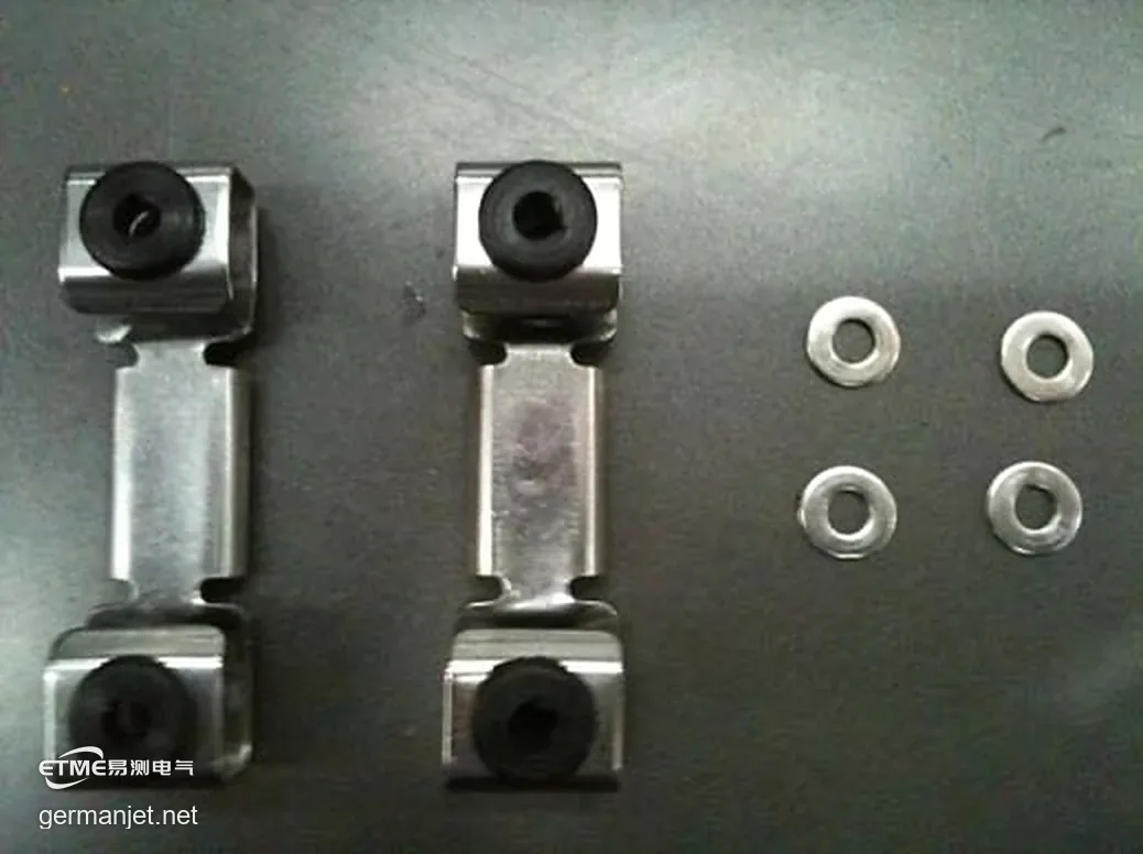
2. Two checks before you start
Step 4 is the only pre-installation check in the whole guide, and it is aimed at the mounting holes on the machine.
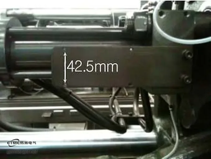
First check: the hole pitch must be 42.5 mm. That dimension is not arbitrary — it matches the centre distance between the two mounting holes in the clip. Get it wrong and the clip either will not fit, or it goes on under permanent pre-load and stops isolating anything.
Second check: both holes must be threaded. Drilled but not tapped, or tapped short, and the screw will not go down to depth. This turns up constantly when retrofitting older machines, where the mounting holes were added later for a different fixing method.

3. Thirteen steps to fit one pair of clips
The steps themselves are simple. Work through them in order:
Steps 1-3, prepare. Unpack and count (2 clips + 4 washers), slide the four washers onto the M4 screws, and lay out the tools: clips, screws, sensor, slipping-type torque screwdriver.
Step 4, check the 42.5 mm hole pitch and the threads. As described above.
Steps 5-6, tighten in two passes. First secure the sensor loosely with two M4 screws, then use the remaining two to fix the clip in the other direction.
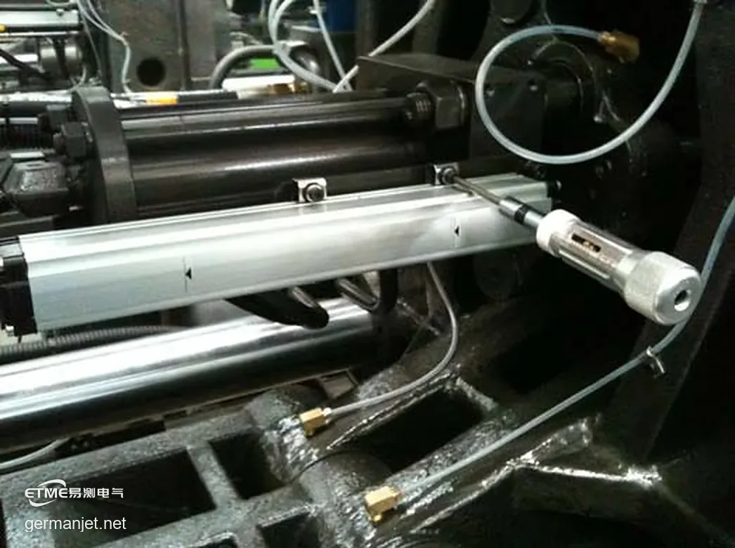
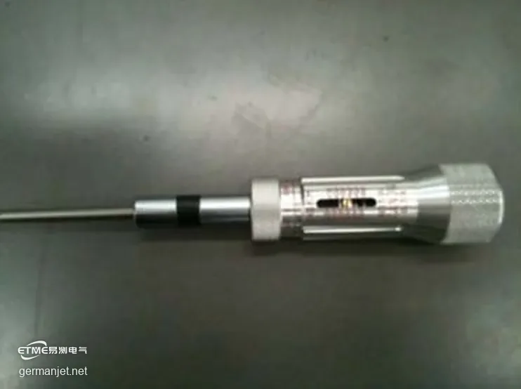
Steps 7-8, set the torque and stop at the click. Set the slipping-type torque screwdriver to 3.5 kgf·cm, drive the screw, and stop the moment it clicks. Do not give it another half turn.
Step 9, visual check. A correct installation leaves the rubber ring slightly compressed and the washer still standing proud, not sunk.
Step 10, remove and check again. Take the clip back off — the black elastomer must show no damage.
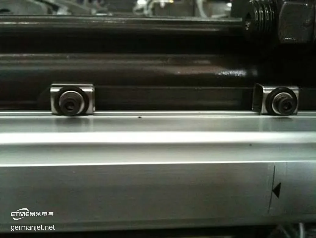
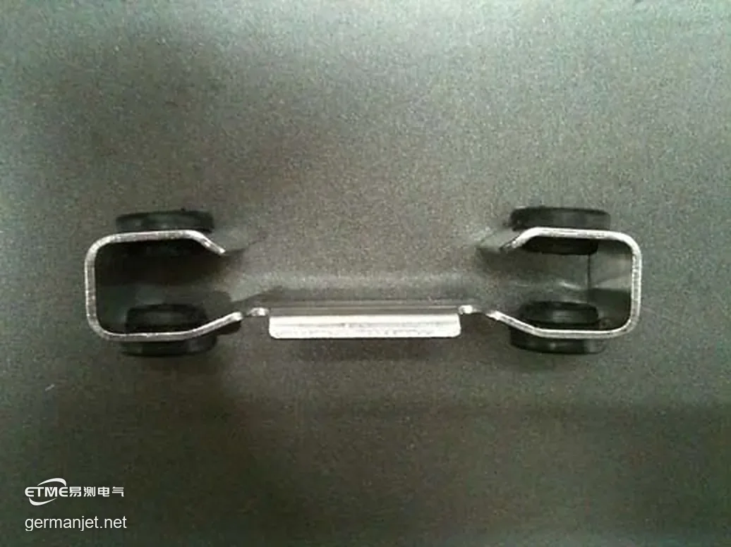
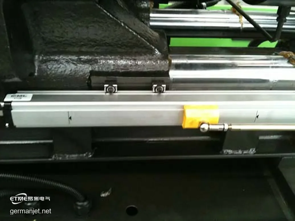
Steps 11-12, finish the clamp-side sensor. Fit the clips to the sensor at the clamp position, same method as steps 1-9. That completes this side.
Step 13, repeat on the injection-side sensor. Fit the clips to the sensor at the injection position, again following steps 1-9.
4. Why the torque must be set at 3.5 kgf·cm with a slipping-type driver
| Torque | What happens |
|---|---|
| Below 3.5 kgf·cm | Screw not seated, a gap remains between clip and machine, vibration still passes |
| 3.5 kgf·cm (standard) | Rubber ring slightly compressed, washer not sunk — the isolating element at its ideal compression |
| Above 3.5 kgf·cm | Elastomer crushed or split, isolation defeated, visible damage on removal |
The point is not to tighten, but to tighten exactly enough. An anti-vibration clip works by interrupting vibration through its elastomer layer, and that elastomer needs room to deform. Over-torque it and the elastomer is crushed into a rigid load path — the clip stops isolating and becomes a solid fixing.
That is why the tool has to be a slipping-type (adjustable) torque screwdriver: at the set torque it slips and spins instead of adding more. And the click-and-stop rule matters equally — keep pushing after the click and you have just undone the torque you set.
5. It clicks but the sensor still will not hold: two causes
The last page of the guide is devoted to a situation that genuinely happens on site: the torque driver has clicked, and the sensor is still not fixed.
Do not reach for more torque. The torque figure protects the isolating element; it is not there to overcome resistance. There are usually only two causes:
Cause one: a broken tap left in the hole. On an older machine, a tap that snapped mid-thread leaves a fragment in the hole. The screw can only travel as far as the fragment, the driver clicks, and the clip was never actually clamped.
Cause two: poor thread quality. A thread that is not cut cleanly makes the screw bind all the way down, and the driver slips before reaching the depth it should.
Both are handled the same way: back the screw out, inspect the hole and the thread, clear it or re-tap, then fit again. Forcing more torque only destroys the elastomer and the screw together.
6. Which part of the vibration these clips actually address
The scope of an anti-vibration clip is specific: it blocks high-frequency vibration travelling from the machine structure into the sensor.
Ejector, injection and clamp motions are all high-speed reciprocating actions, and the machine mounting bracket generates high-frequency vibration at each stroke. Fix the sensor rigidly to that bracket and the vibration runs straight into the sensor core — showing up as a jittering position reading, not as simple accuracy drift.
In practice the cause often lies nowhere near the sensor. On one injection moulding site visit we found ten machines where only one ejector sensor read erratically. The culprit was a mounting plate that was too thin: at high speed the plate itself resonated like a tuning fork and fed the vibration straight into the sensor. Fitting an anti-vibration base eliminated the problem. The full investigation is written up in Ten Injection Presses, One Jittering Ejector Sensor.
If your reading is already jittering, start by separating the sensor, the cable and the controller with the procedure in the dry battery isolation method, so you know whether the fault sits in the measurement chain or in the mechanical installation. For general installation practice see the hydraulic cylinder displacement sensor guide.
7. Which sensor series these clips fit
Anti-vibration clips mount between the sensor and the machine, and they fit every Germanjet series used for injection moulding position measurement:
| Mounting position | Typical series |
|---|---|
| Inside large presses (injection / clamp / ejector) | 19 Series H-type in-cylinder magnetostrictive position sensor |
| Extra-long stroke injection / clamp | 19 Series P-type external magnetostrictive position sensor |
| Fully digital position sensors (injection / clamp / ejector) | 17 Series hydraulic cylinder integrated magnetostrictive position sensor |
| External mounting, standard stroke | 18 Series external magnetostrictive position sensor |
On older machines running several position sensors, there is one further step worth taking: move the position signals from analogue to a bus output and cut the amount of wiring in the cabinet. A digital CANbus integration module connects Start-Stop output sensors directly to a CANbus network, and less wiring means less of the routing interference described above.
8. The numbers to check against on site
Pull these out when you are fitting:
| Item | Standard | Sign of failure |
|---|---|---|
| Mounting hole pitch | 42.5 mm | Will not fit, or the elastomer sits permanently deformed |
| Tightening torque | 3.5 kgf·cm, slipping-type driver, stop at the click | Too low and it vibrates loose; too high and the elastomer is crushed |
| Washers | One per M4 screw, four in total | Screws drive straight into the elastomer |
| Acceptance | Rubber ring slightly compressed, washer not sunk, elastomer undamaged on removal | Washer sunk, or elastomer cracked |
This article is based on the Germanjet "Isolation Mounting Installation Instruction" issued on 31 March 2011. All 13 steps and every figure quoted here come from the original factory document.
Frequently Asked Questions
Q: Can the washers be left out of an anti-vibration clip installation?
No. The washer spreads the screw head load across the clip; without it the screw drives straight into the elastomer and turns the isolating joint back into a rigid one. Washers are supplied with the clips — two clips, four washers — so there is nothing to source separately. If the pack is short one, do not substitute a plain flat washer: the washer thickness is matched to the compression of the clip's elastomer.
Q: Can an ordinary screwdriver be used instead of a torque screwdriver?
Not recommended. The standard is 3.5 kgf·cm, and acceptance depends on the rubber ring being slightly compressed with the washer still standing proud. An ordinary screwdriver relies on feel and overshoots easily; once the elastomer is crushed the isolation is defeated, and you will see the damage when the clip comes off. A slipping-type torque driver slips at the set torque and is the only way to guarantee you do not exceed it. Once it clicks, do not add more.
Q: The torque driver clicked but the sensor is still not fixed. Why?
The factory guide names two causes. First, a broken tap left inside the mounting hole: the screw can only travel as far as the fragment, so the driver clicks without the clip actually being clamped. Second, poor thread quality: a thread that binds all the way down makes the driver slip before reaching the correct depth. Both are handled the same way — back the screw out, clear the hole or re-tap, then fit again. Do not force more torque; it only destroys the elastomer and the screw together.
Related Products




Related Applications
Ejector Sensor Jitter on an Injection Moulding Machine: From Mounting Plate Resonance to the Standard Clip Fitting
View Details
Series 19H Cylinder-Integrated Process Displacement Sensor Application Cases
View Details
Series 19P External Rod Process Displacement Sensor Application Cases
View Details