Ejector Sensor Jitter on an Injection Moulding Machine: From Mounting Plate Resonance to the Standard Clip Fitting
An injection moulding plant reported a jittering ejector sensor reading. To pin the problem down we ran all ten machines on the line up to maximum ejector speed and watched each reading in turn: only one of the ten jittered, and the other nine stayed steady at full speed. That ratio is the most useful clue on the job. A faulty sensor would not single out one machine in ten; one in ten points to a mechanical condition specific to that machine.
Read the waveform before touching the sensor
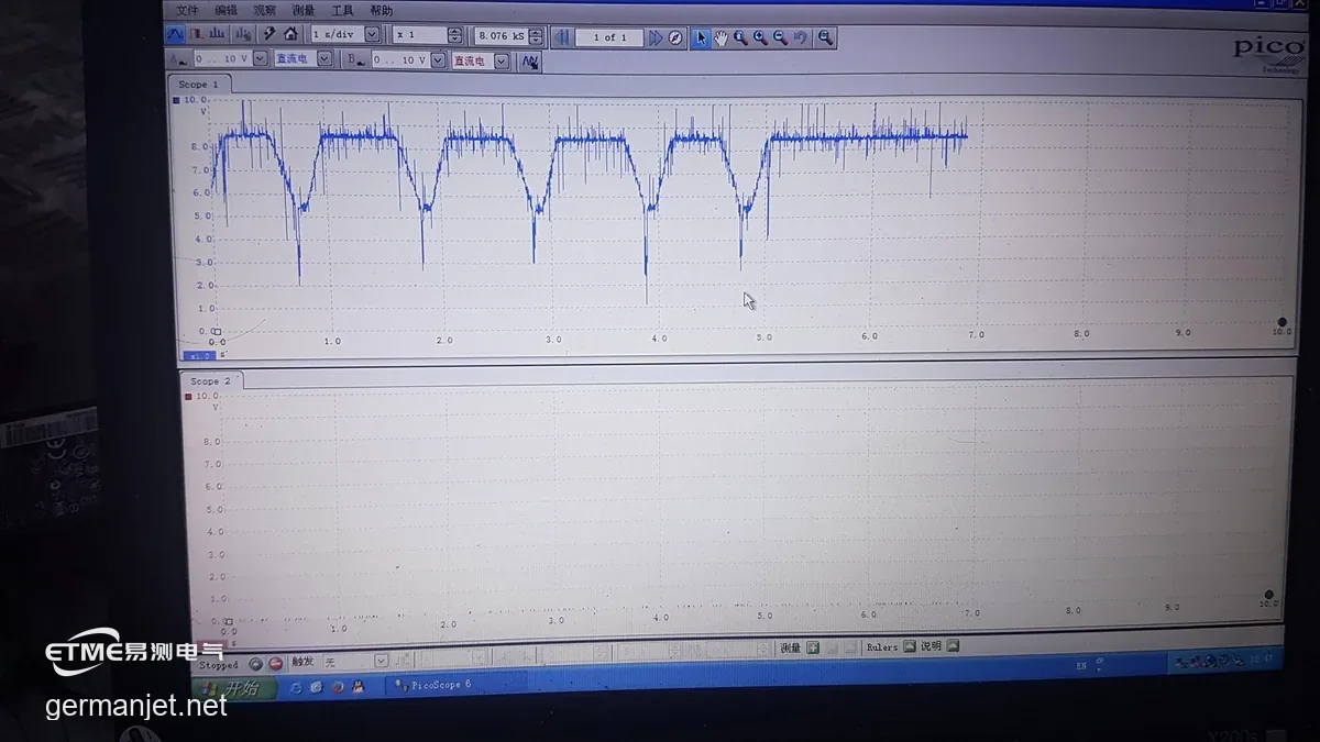
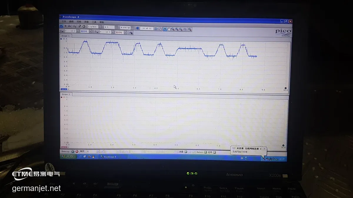
The first step on site is not to swap the sensor but to bring the waveform up. There are two shapes to look for. If the reading jitters while the ejector is standing still and the machine is at rest, the direction is supply or cable interference. If the noise appears only while the ejector moves and disappears the moment it stops, the direction is mechanical vibration reaching the sensor. This machine was the second case: flat with the ejector parked, noise the moment it accelerated, and worse the faster it ran.
The cause was not in the sensor: a mounting plate ringing like a tuning fork
Tracing the vibration back led to the mounting plate. The machine that jittered was the smallest press on the line: less room around the sensor, and a mounting plate thinner and less rigid than the one fitted to the larger machines. At ejector speed that plate is excited into resonance of its own, and the vibration travels down the cantilever into the sensor core, taking the reading with it.
That mechanism gives the fault a signature: it gets worse the faster the machine runs and is invisible at low speed, which is why a machine can pass its acceptance run and only show the problem once it runs at production speed. It also settles the second question — a new sensor does not help. Fit a new sensor into the same mounting condition and it will jitter just the same. No sensor was replaced on this job.
The fix: an anti-vibration base, and the waveform cleaned up on the spot
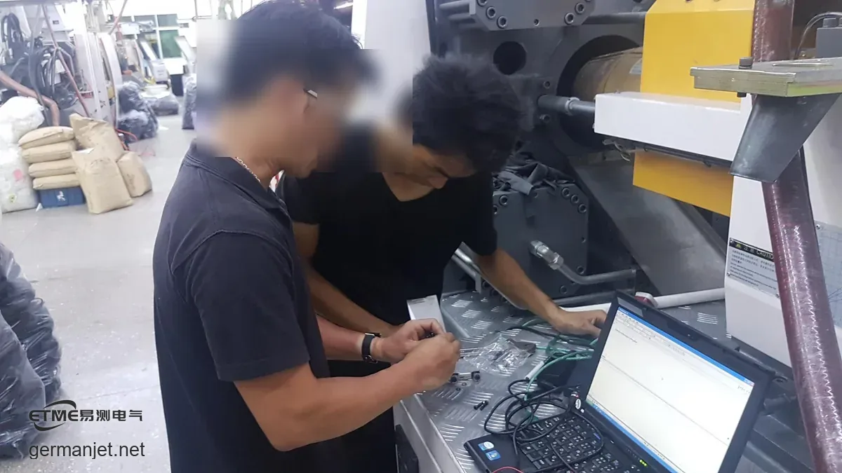
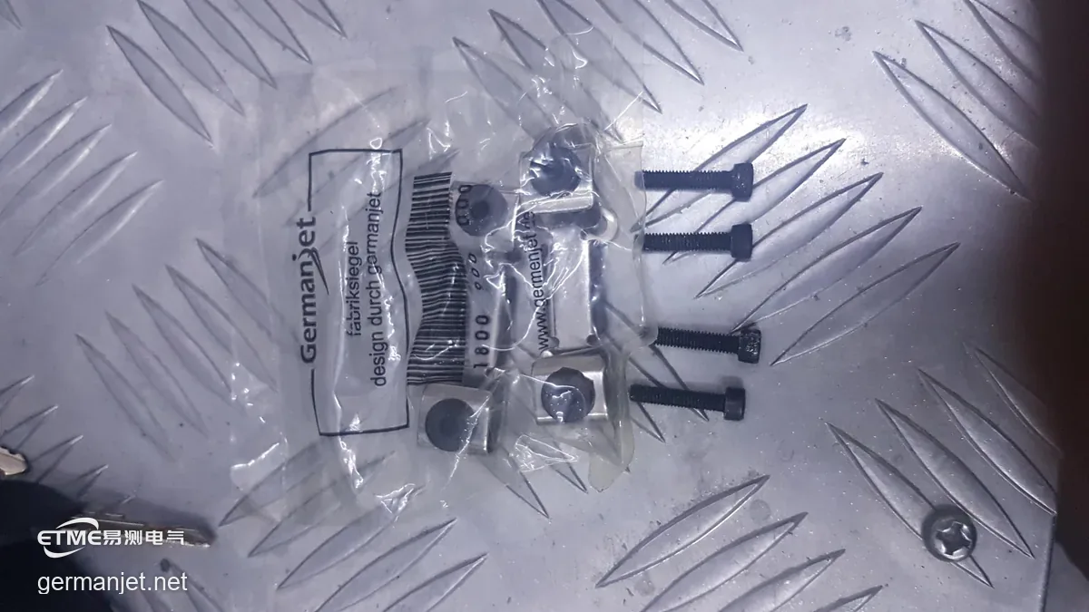
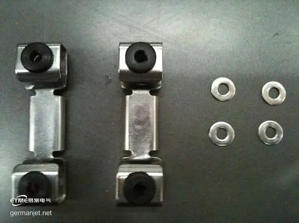
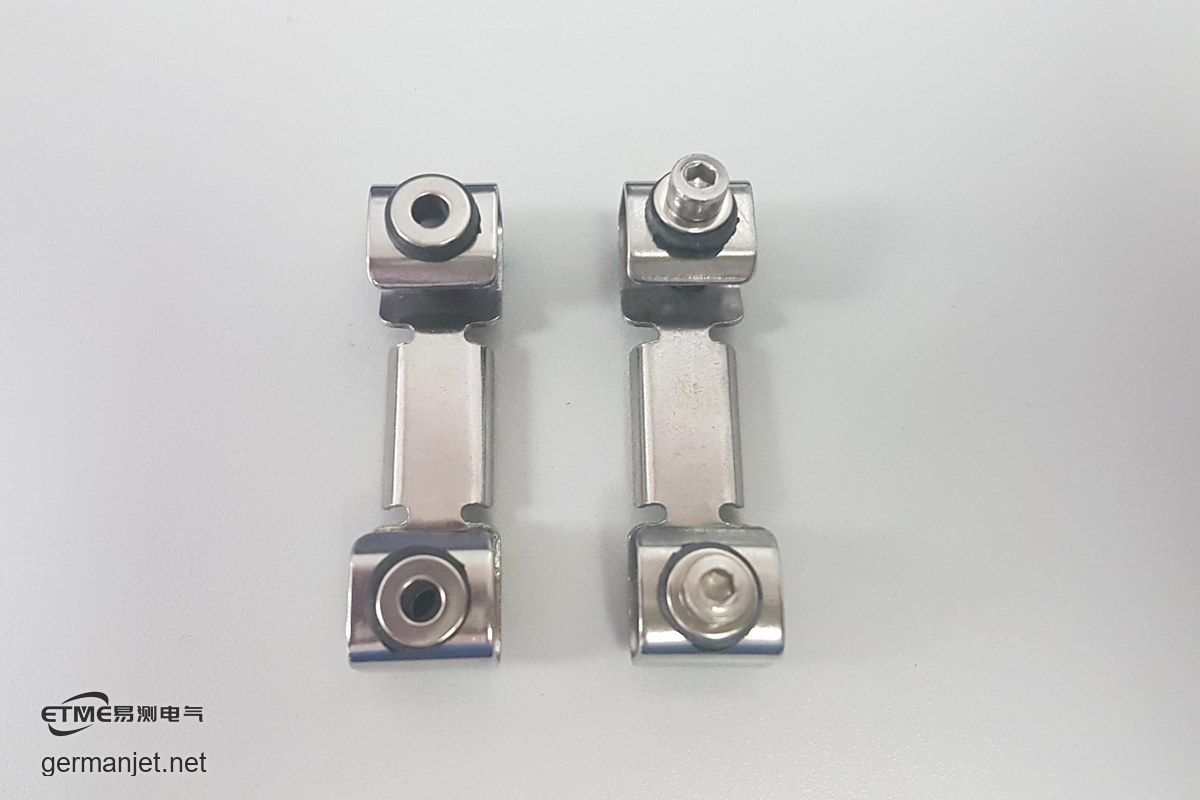
The fix was to replace the plain mounting plate with an anti-vibration base, with the anti-vibration mounting clips and washers fitted to the original factory procedure, breaking the rigid connection between the sensor and the mounting plate. On re-test the waveform at the same measuring point flattened out immediately and the noise disappeared; a second run of all ten machines at full speed put this machine in line with the other nine.
Fixing the standard: a 42.5 mm hole pitch and 3.5 kgf·cm of torque
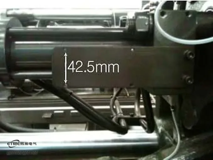
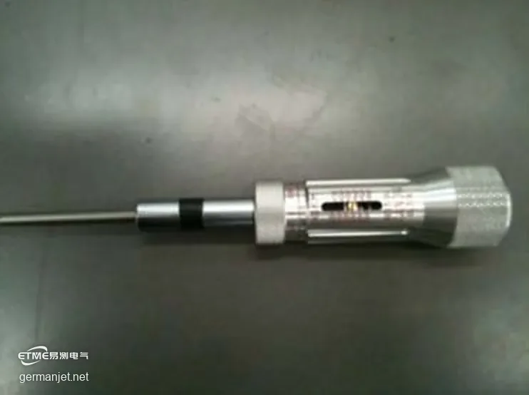
An anti-vibration base only does its job if it is fastened correctly. The factory procedure turns on two numbers that have not moved in over a decade: a hole pitch of 42.5 mm and a tightening torque of 3.5 kgf·cm. Check the pitch and confirm the threads are cut before fitting. Torque has to be applied with a slipping-type torque driver and stopped the moment it clicks — and not topped up afterwards. Too much crushes the elastomer and turns the isolation back into a rigid joint; too little leaves the screw unseated and the base floating on the machine.
Acceptance is judged in three places: the rubber ring on the clip is slightly compressed, the washer does not sink, and the black elastomer is undamaged when the clip is taken off. If the driver has clicked but the sensor is still not held, the factory guide names two site causes — a broken tap left in the hole, or poor thread quality making the screw turn unevenly. Both mean backing the screw out and clearing the hole or re-tapping. Do not answer it with more torque; that takes the clip and the screw out together.
The two details that get skipped
The first is the washer. A pack contains two clips and four washers, and not one of the four can be left out from under an M4 screw. The washer spreads the screw head load across the clip; without it the screw drives straight into the elastomer, turning the isolating joint back into a rigid one by hand — and by the time you take it off the black elastomer is usually already crushed.
The second is installation over-travel. Several machines in the same batch showed the same state: at the bottom of the ejector stroke the slider on the sensor had passed the black mark on the housing. Crossing that line means the effective stroke of the sensor does not fully cover the actual stroke of the machine, so the sensor takes extra mechanical shock at both ends of every cycle. It has to be measured at installation — once the machine is assembled, no parameter setting will put it back.
How to judge this class of fault
Three rules cover it, and they hold for clamp and ejector sensors alike. First, separate the direction: does the noise appear only with the movement? Second, check the mechanics before the sensor: is the mounting plate thick enough and rigid enough, and on a small machine in particular. Third, fix from the mounting outwards: fit an anti-vibration base, follow the standard hole pitch and torque for the clips, and only consider the sensor last.
This page records a single site visit and fitting job. Customer names and machine numbers have been removed, and no specific customer project is disclosed. Hole pitch, tightening torque and acceptance criteria follow the original factory Anti-Vibration Mounting Clip Installation Guide and the delivery documents for the equipment actually used.
On-Site Photos