Digital/CANbus Integration Module
8-channel digital CANbus module for Start/Stop scales, CAN 2.0A, 500 kbit/s
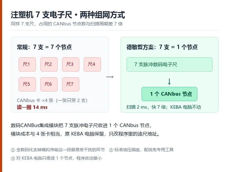
The Germanjet eight-channel digital/CANBus integration module is mainly used with 1830 digital scales that provide a Start/Stop signal output, and meets the requirement of collecting eight sets of digital displacement readings into a single CANbus node. For the controller, a scan cycle that would have required reading eight nodes can now be completed by reading one, greatly improving the efficiency of the control computer and the CANbus. From a cost-effectiveness standpoint it is also the fieldbus solution with the best value. The scale outputs real-time displacement data as a Start/Stop digital pulse train to the module installed in the control cabinet, which converts the multiple displacement readings into the CANbus protocol, aggregates them into a single CANbus node and transmits them to the CANbus input of the controller. The module contains a dedicated 24V filtering and voltage-regulating system, providing the most complete power supply solution for the measurement and removing the unstable readings caused by sharing a 24V supply on the machine. This approach requires no changes to existing equipment configuration such as the control computer and wiring, and fully realises the benefits of a fieldbus installation.
Product Overview
The eight-channel digital/CANBus integration module is mainly used with 1830 digital scales that provide a Start/Stop signal output, and meets the requirement of collecting eight sets of digital displacement readings into a single CANbus node. For the controller, a scan cycle that would have required reading eight nodes can now be completed by reading one, greatly improving the efficiency of the control computer and the CANbus; from a cost-effectiveness standpoint it is also the fieldbus solution with the best value.
The module is used together with the 1830 digital scale. The scale sends real-time displacement data in digital format to the module installed in the control cabinet, which converts the multiple displacement readings into the CANbus protocol, aggregates them into a single CANbus node and transmits them to the CANbus input of the controller.
The module contains a dedicated 24V filtering and voltage-regulating system, providing the most complete power supply solution for displacement measurement and removing the problem of unstable readings caused by sharing a 24V supply on the machine.
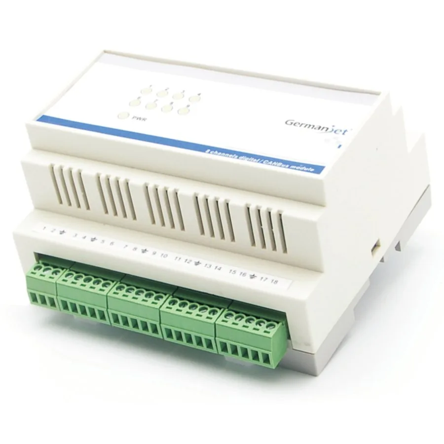
This approach requires no changes to existing equipment configuration such as the control computer and wiring, and fully realises the benefits of a fieldbus installation. The module uses DIN rail mounting and provides a PWR lamp plus eight channel LEDs so that wiring and magnet sensing can be verified channel by channel.
Operating Principle
The module processes the Start/Stop digital pulse signals of eight 1830 digital scales together, converts them into the CANbus protocol and outputs them as a single CANbus node, so the controller only has to read one node to obtain eight displacement values. The data format is CANbasic (CAN 2.0A), the transmission rate is 500 kbit/s, bus length is under 100 m and resolution is 0.01 mm. A dedicated built-in 24V filtering and voltage-regulating system provides a complete power supply for the measurement. The PWR lamp on the module panel lighting up indicates a normal 24V supply, and each channel LED lighting up indicates correct wiring with the scale sensing its magnet, making it easy to verify the wiring channel by channel on site.
Typical Applications
Technical Specifications
| Order number | 1800 951 020 |
|---|---|
| Output | CANbus digital output |
| Input | 8-channel Start / Stop digital pulse |
| Data format | CANbasic: CAN 2.0A |
| Transmission speed | Rate: 500 kbit/s; cable length: < 100 m |
| Resolution | 0.01 mm |
| Repeatability | Full scale < ±0.001% (minimum ±2.5 μm) |
| Non-linearity | Full scale < ±0.01% (minimum ±40 μm) |
| Update time | 2.0 ms up to 4800 mm |
| Supply voltage | +24 Vdc (20.4 – 28.8 Vdc) |
| Input protection | Polarity protection to −30 Vdc, overvoltage protection to 36 Vdc |
| Current consumption | 800 mA (depending on range) |
| Dielectric strength | 500 Vdc (DC ground to machine earth) |
| Operating temperature | 0 – 55 °C, non-condensing |
| EMC testing | Emission EN61000-6-3, immunity EN61000-6-2, EN61000-4-2/3/4/6 |
| Weight | 0.45 kg |
| Dimensions | 106 × 90 × 58 mm (W × H × D) |
Models and Output Signals
Dimensions and Wiring Diagrams
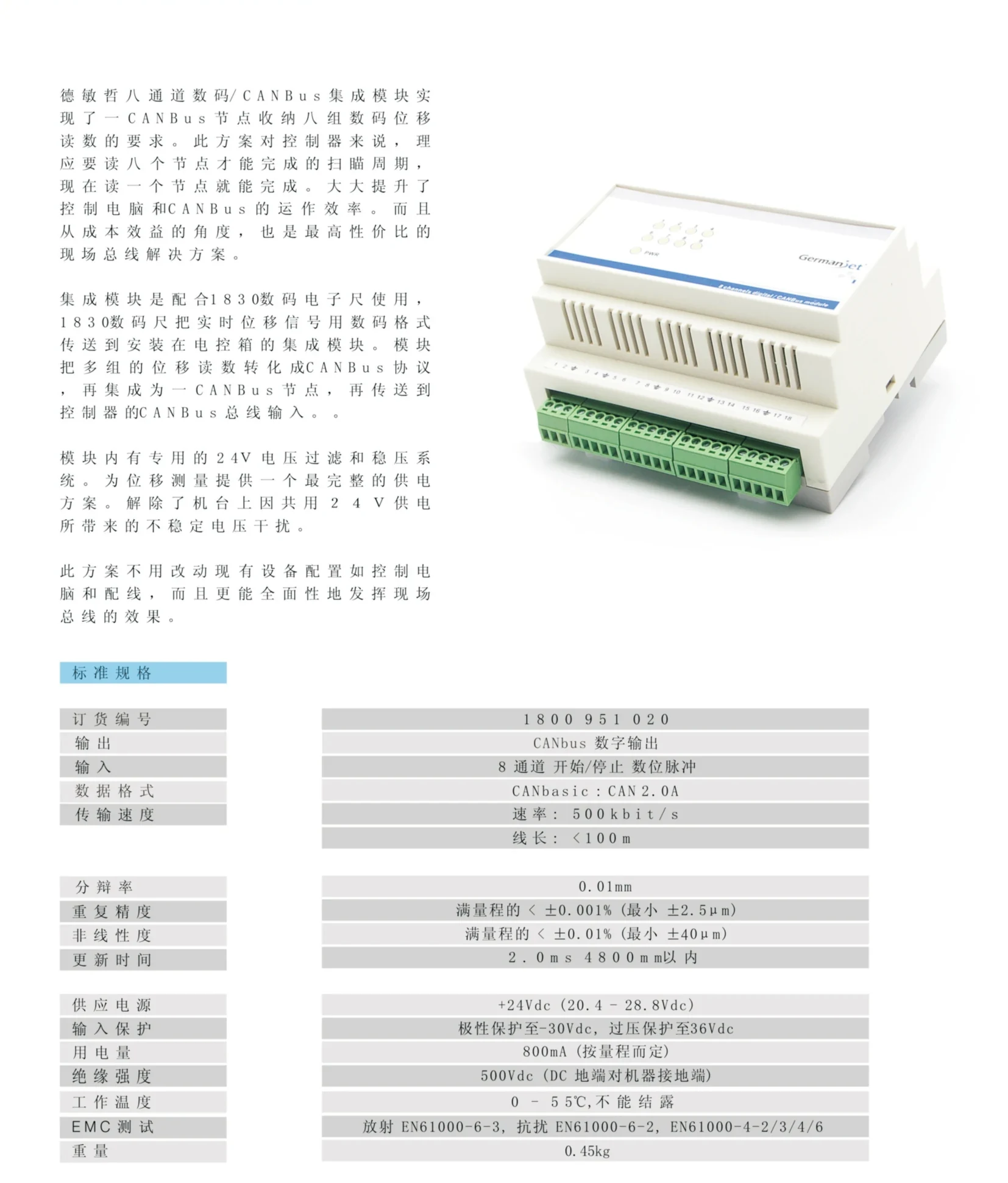
Digital/CANBus integration module - overview and specifications
Product overview, module photo and standard specification table (data format, transfer rate, accuracy and all parameters)
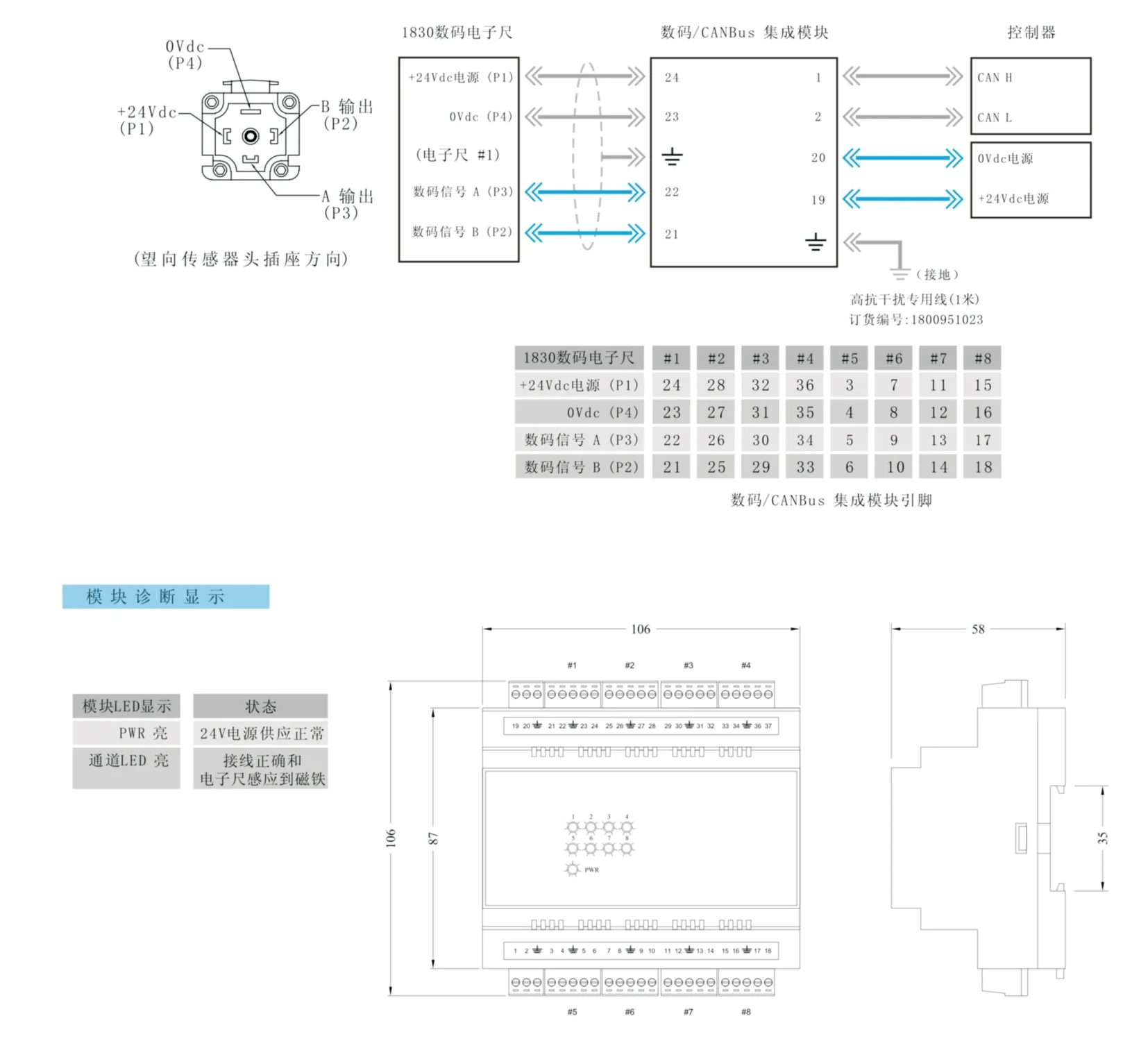
Digital/CANBus integration module - wiring diagram and dimensions
Wiring diagram (1830 digital scale to module to controller), eight-channel pin mapping table, diagnostic indication and outline dimensions
Installation Precautions
- This module must be used with 1830 digital scales that provide a Start/Stop signal output; it cannot perform displacement measurement on its own.
- Wiring (looking at the sensor head socket): sensor socket — P1 = +24 Vdc supply / P2 = B output (digital signal B) / P3 = A output (digital signal A) / P4 = 0 Vdc; module side — terminal 24 = +24 Vdc supply / 23 = 0 Vdc supply / 22 = digital signal A / 21 = digital signal B, plus earth; controller side — CAN H / CAN L to the bus, plus 0 Vdc and +24 Vdc supply.
- Eight-channel pin mapping: +24 Vdc supply (P1) corresponds to terminals 24 / 28 / 32 / 36 / 3 / 7 / 11 / 15 for scales #1–#8; 0 Vdc (P4) to 23 / 27 / 31 / 35 / 4 / 8 / 12 / 16; digital signal A (P3) to 22 / 26 / 30 / 34 / 5 / 9 / 13 / 17; digital signal B (P2) to 21 / 25 / 29 / 33 / 6 / 10 / 14 / 18.
- Supply is +24 Vdc (20.4 – 28.8 Vdc), polarity protection to −30 Vdc, overvoltage protection to 36 Vdc, current consumption 800 mA. Do not reverse or exceed these limits.
- The CANbus network must have the node address and terminating resistors set correctly; the transmission rate is 500 kbit/s and the bus length should be under 100 m.
- The module contains a dedicated 24V filtering and voltage-regulating system. When the machine shares a 24V supply, confirm the voltage is stable to avoid interference and unstable readings.
- Operating temperature 0 – 55 °C, non-condensing. Install inside the control cabinet, away from direct oil mist, moisture and metal dust.
- Module LED states: PWR on = normal 24V supply; channel LED on = correct wiring and magnet sensed by the scale. This allows each of the eight scales to be checked for wiring and magnet state.
- The module uses DIN rail mounting, measures 106 × 90 × 58 mm and weighs 0.45 kg. Use the high-immunity dedicated cable (order number 1800 951 023) and avoid routing parallel to power cables.
Pricing Notes
The price of the digital/CANbus integration module depends on quantity and the cable supplied. Please provide the number of scales, measuring range and controller CANbus interface specification for a quotation.



Technical Articles
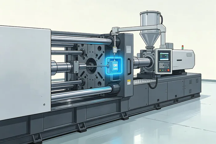
Injection Moulding Machine Displacement Sensor: Three Ruler Positions and Wiring
Read More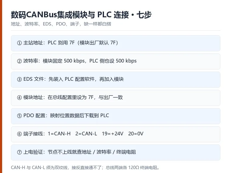
Connecting a Digital CANbus Integration Module to a PLC: Seven Configuration Steps
Read More