Connecting a Digital CANbus Integration Module to a PLC: Seven Configuration Steps
Connecting a Germanjet digital CANbus integration module to a PLC comes down to seven steps: power, address, baud, EDS, PDO mapping, terminal wiring, and a live position check. This article walks the whole chain so the module publishes positions on the first attempt instead of the third.
The values behind each step
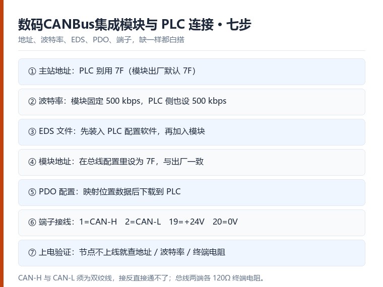
- Master address — the module is a CANbus slave with a factory node address of hex 7F, or 127 decimal. The PLC master must use a different address — hex 01, for example. If the two collide, neither device comes onto the bus.
- Baud rate — the module's CAN baud rate is fixed at 500 kbps, so set the PLC to 500 kbps as well. A baud mismatch is the most common reason for "the wiring is all correct but it will not talk".
- EDS file — if the PLC engineering tool needs an EDS file to recognise a CAN bus node, import it first; the Germanjet digital CANbus integration module then appears in the bus configuration by name.
- Module address in the configuration — in the bus configuration software, set the communication address to hex 7F (127), matching the factory address of the module.
- PDO mapping — configure the PDO objects on the CAN bus master and map the position data you need to read. Confirm master address, slave address and PDO objects, then download the configuration to the PLC.
- Terminals — the module has 20 terminals, but only four are used: terminal 1 to CAN-H (CAN+), terminal 2 to CAN-L (CAN−), terminal 19 to the supply positive +24 Vdc and terminal 20 to the supply negative 0 Vdc. CAN-H and CAN-L are one twisted pair and must not be swapped — reversed, the bus simply will not work.
- Power-on check — once the supply is on, the bus should run and the PLC should see the module online with every channel reading. If the node does not come online, check in this order: address collision, baud rate, termination (120 Ω at each physical end) and CAN-H / CAN-L polarity.
Configuration is not complicated, but every step is a hard condition — address, baud rate, EDS, PDO and terminals. Miss one and nothing works. Walk the seven steps and several electronic rulers sharing one bus node is a finished job.
The seven steps
- Supply — 24 V DC to the module, clean and stable. A module fed by a noisy supply publishes noisy positions.
- Node ID — set a unique address for the module on the bus.
- Baud — match the master. Check termination: 120 Ω at each physical end of the bus.
- EDS import — load the module's EDS file into the PLC engineering tool so the objects appear by name.
- PDO mapping — map the position channels you need into the TPDO; most modules carry several channels, so map only what the PLC logic reads.
- Terminal wiring — connect the input channels from the rulers (4-20 mA, 0-10 V or SSI per the input type), keep shields single-ended at the controller.
- Live check — move one axis and watch the position object change in the PLC. If it does not, check the node state (operational) before the wiring.
Where people get stuck
- EDS imported but no data → the node is not in operational state. Start it.
- One channel reads, others do not → mapping, not the bus. Map each channel you need.
- All channels jump together → supply or shield on the input side, before the module.
- Intermittent whole-bus errors → termination or baud, almost never the sensor.
The module that lets seven electronic rulers share one node is explained in seven rulers on one CANbus node, and the underlying CANopen frames in CANopen communication examples. For analogue outputs that jump, see three-step dry battery isolation method.
Frequently Asked Questions
Q: EDS imported but no position arrives. What now?
Check the node state first — it must be Operational. Then verify the PDO mapping and the COB-ID on both sides.
Q: One channel reads, the others do not.
That is the mapping, not the bus. Map every channel the PLC logic needs into the TPDO.
Related Products
Related Applications
Series 19D Split-Type Process Displacement Sensor Application Cases
View Details
Multi-Industry Application Cases for Magnetostrictive Displacement Sensors
View Details
Series 19F Flexible Process Displacement Sensor Application Cases
View Details