
Checking a Magnetostrictive Displacement Sensor with a Multimeter: 5 Steps to Locate the Fault
To tell a magnetostrictive displacement sensor good from bad, five multimeter steps localise the fault to supply, output, lamps, insulation or install. When a field sensor "has no signal", the first move is not necessarily to remove it and send it for repair. With a multimeter, the five steps below can quickly decide whether the problem is the sensor body, or the supply, wiring, position magnet or installation. Decide correctly, then decide whether to return it to the factory or handle it on site — time and money saved.
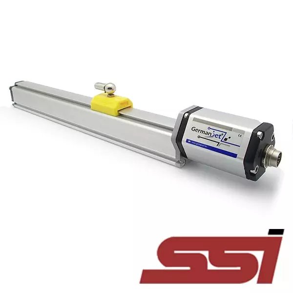
Step 1: measure the supply voltage
First confirm that the sensor supply is normal. Most electronics heads work at +24 V (20.4–28.8 V); Series 13 also accepts +12 V. Reverse polarity −30 V and over-voltage 36 V are protection limits; isolation is typically 500 Vdc; voltage-output load ≥5 kΩ. Set the multimeter to DC voltage and measure across the supply terminals: voltage is 0 → check the power supply and wiring; voltage is normal → go to the next step. Many "no output" cases are simply a broken supply or a loose wire.
Step 2: measure the output signal
With the supply normal, measure the signal output. Analog (0-10 V / 4-20 mA): move the position magnet slowly along the rod and watch whether the output voltage/current changes linearly with position. If 4-20 mA does not move smoothly as the magnet slides, the signal path is at fault, not the cylinder. If the voltage is constant or jumps, the signal path has a problem. Fieldbus types (SSI/CANopen/EtherCAT and others): analog voltage cannot be measured directly; focus on the fieldbus terminating resistor, address and shield earthing (see fieldbus data-loss troubleshooting).
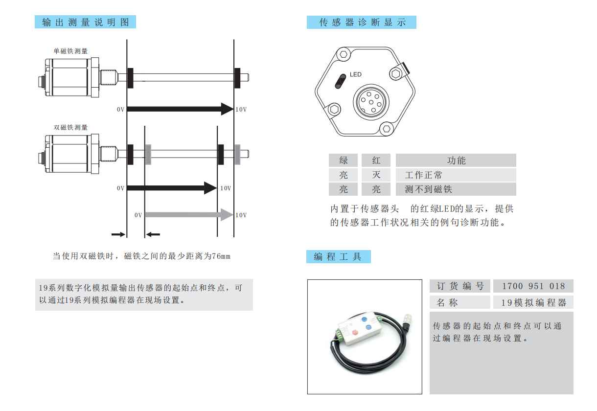
Step 3: look at the LED diagnostic lamps
Germanjet sensors have built-in LED diagnostics: green on, red off = normal; both lamps on = magnet not detected (including leaving the valid stroke / over-range). Full lamp table: electronics-head LEDs. When both lamps are on, first move to mid-stroke: if the lamps recover it was over-range; if they stay dual-on, check a fallen / reversed magnet or the air gap.
Step 4: measure insulation resistance
With the multimeter resistance range (or a megohmmeter) measure insulation of the signal cores to earth (the housing). Insulation that is too low (for example tens of kΩ or below) indicates internal water ingress or damaged insulation, common on high-temperature, humid or corrosive-gas sites. Insulation problems usually need a return to the factory; they are hard to repair on site. Also check in passing whether the cable is open-circuit — an internal break produces complete no-output.
Step 5: distinguish body vs. installation
If supply, output, insulation and the magnet are all normal but the reading is wrong, focus on installation: whether the position magnet is coaxial with the rod, whether there is mechanical interference, whether the range has entered a dead zone (dead zones exist at both ends of the effective range), and whether a loose mounting is causing position drift. A test magnet at a known position as a comparison can further separate "body" from "installation".
Summary
After the five steps, the large majority of problems can be located to a specific link: power/wiring → sensor body → position magnet → insulation → installation. Return to the factory only after the body is confirmed faulty; other problems can be handled on site. If questions remain after troubleshooting, remote diagnostic support is available.
Frequently Asked Questions
Q: The sensor has no signal. Do I have to remove it and send it for repair?
Not before trying a multimeter. Work through five steps: measure the supply voltage, measure the output signal, read the LED diagnostics, measure insulation resistance, and separate the sensor body from the installation. Those five steps localise the fault to supply and wiring, the sensor body, the position magnet, insulation or installation, so you only return it once the body is confirmed faulty and handle everything else on site.
Q: Why is the supply measured first?
Because it is the most easily overlooked and most frequently faulty link. Most electronics heads run at +24 V (20.4 to 28.8 V), and Series 13 also accepts +12 V. Set the multimeter to DC voltage and measure across the supply terminals: zero volts means checking the supply and wiring, and a normal voltage means moving to the next step. Many no-output cases are simply a broken supply or a loose wire.
Q: How do I judge an analog output?
With the supply normal, measure the signal output: move the position magnet slowly along the rod and watch whether the output voltage or current changes linearly with position. A voltage that is constant or jumps indicates a problem in the signal path. A fieldbus type such as SSI, CANopen or EtherCAT cannot be measured as an analog voltage, so focus on the terminating resistor, node address and shield earthing.
Q: What do two lit LEDs mean?
Both lamps on means the magnet is not detected, which covers a magnet that has left the valid stroke as well as over-range. First move the piston to mid-stroke: if the lamps recover it was over-range, and if they stay dual-on, check whether the magnet has fallen off, been fitted reversed, or has the wrong air gap. The normal state is green on and red off.
Q: When does the sensor have to go back to the factory?
Insulation problems almost always do. Measure insulation of the signal cores to earth, the housing, with the resistance range or a megohmmeter; insulation below tens of kΩ indicates internal water ingress or damaged insulation, common on high-temperature, humid or corrosive-gas sites, and it is hard to repair on site. While there, also check the cable for an open circuit, since an internal break produces complete no-output. If supply, output, insulation and magnet are all normal but the reading is wrong, focus on installation: coaxiality of the magnet, mechanical interference, the range entering a dead zone, or a loose mounting causing drift.
Related Products



Related Applications

Multi-Industry Application Cases for Magnetostrictive Displacement Sensors
View Details
Series 17 Hydraulic Cylinder Integrated Magnetostrictive Displacement Sensor Application Cases
View Details
Series 12 General-Purpose Magnetostrictive Displacement Sensor Application Cases
View Details