
Magnetostrictive Displacement Sensor Reading at Zero: End of Stroke or Broken Wire?
A position stuck at 0 is not always a failed magnetostrictive displacement sensor; 4-20 mA can tell end-of-stroke from an open cable. When the PLC position drops to 0, the first reflex is often to replace the sensor. Split the output first: 4-20 mA can tell “at the start of stroke” from “the cable is open”; 0-10 V cannot. Output types: eight interfaces compared. Wiring: Series 191 analogue.
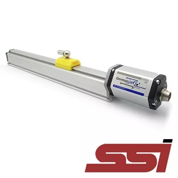
Current or voltage first
Series 16 current is 161, voltage 160; Series 19 often 191 / 190; Series 18 current 184 / 185, voltage 180; Series 12 current 121, voltage 120. A current output on a voltage channel — or the reverse — also sticks at 0 or full scale. That is not the magnet at the end stop.
4-20 mA: using the live zero
In normal running, at the start of the effective stroke the loop is still about 4 mA, not 0. An open cable, a loose plug or lost supply drops the loop near 0. Series 18 code 185 is 20-4 mA reversed: near the far end the loop is close to 4 mA; an open wire still falls near 0, not to 20 mA.
- PLC: set the under-range alarm below 4 mA; do not set it at 0, or a broken loop stays invisible. Do not treat a healthy 4 mA as a fault.
- Meter: measure current at the sensor connector, not only the PLC register. Machine parked mid-stroke and current still near 0 → check cable, plug and supply. Mid-stroke still about 12 mA while the PLC shows 0 → check channel type, range and scaling.
- Head lamps: green on / red off means measuring is healthy; both on means the magnet is not seen (including out of the valid zone). That is not the same as an open loop. Lamps: electronics-head LEDs. Supply and loop order: five meter steps, no output, three steps.
0-10 V: 0 V does not prove a break
True mechanical zero, an open signal wire, or a channel pulled to earth can all show 0 V. A voltage input has no live zero.
- Nudge the magnet (or jog the cylinder a little): if voltage moves, you are likely near the start; if it stays nailed at 0, check the cable and the channel first.
- Measure on the sensor terminals, not only the screen.
- If the controller can take current, prefer 4-20 mA. Long-cable drop: long-cable transmission.
Five steps on site
- Confirm current or voltage, and that the PLC channel matches.
- Read the head lamps; rule out “magnet not detected” first.
- Measure at the sensor, not only on the cabinet terminals.
- Move the magnet and see whether the value follows.
- Then check PLC scaling, diagnostic limits and shield earth. Interference jumps: signal jump troubleshooting.
Prefer current when the controller can take it. Analogue versus fieldbus: 4-20 mA or fieldbus.
Frequently Asked Questions
Q: What should 4-20 mA read at the start of stroke?
Still about 4 mA, not 0. Near 0 is when you first check cable, plug and supply. Do not declare 4 mA a fault.
Q: Does 0 V on 0-10 V mean a broken wire?
Not by itself. True zero, an open cable and a channel to earth can all be 0 V. Nudge the magnet and measure at the sensor terminals. Prefer 4-20 mA if the controller allows it.
Q: PLC shows 0 but the sensor still has 12 mA. Whose fault?
The loop is alive. Check that the PLC channel is a current input and that range and scaling map 4-20 mA correctly. A current output on a voltage channel also sticks at 0 or full scale.
Q: Both LEDs on — is that an open cable?
No. Both on means the magnet is not detected, including out of the valid zone. For an open loop, measure supply and loop current at the connector. See the LED article.
Related Products



Related Applications

Multi-Industry Application Cases for Magnetostrictive Displacement Sensors
View Details
Series 17 Hydraulic Cylinder Integrated Magnetostrictive Displacement Sensor Application Cases
View Details
Series 12 General-Purpose Magnetostrictive Displacement Sensor Application Cases
View Details