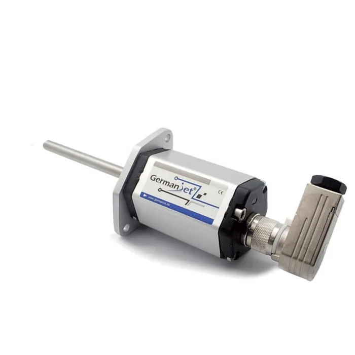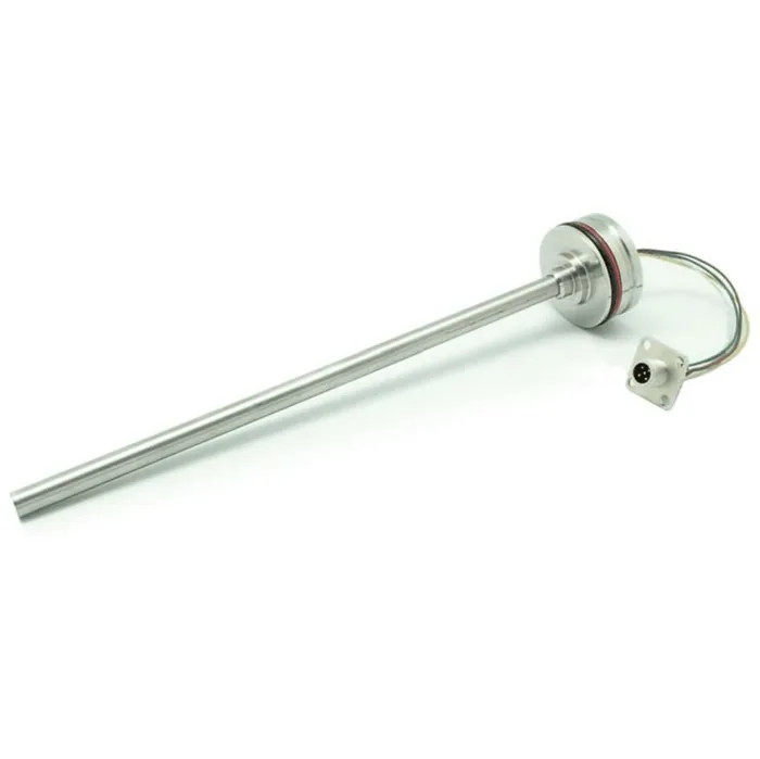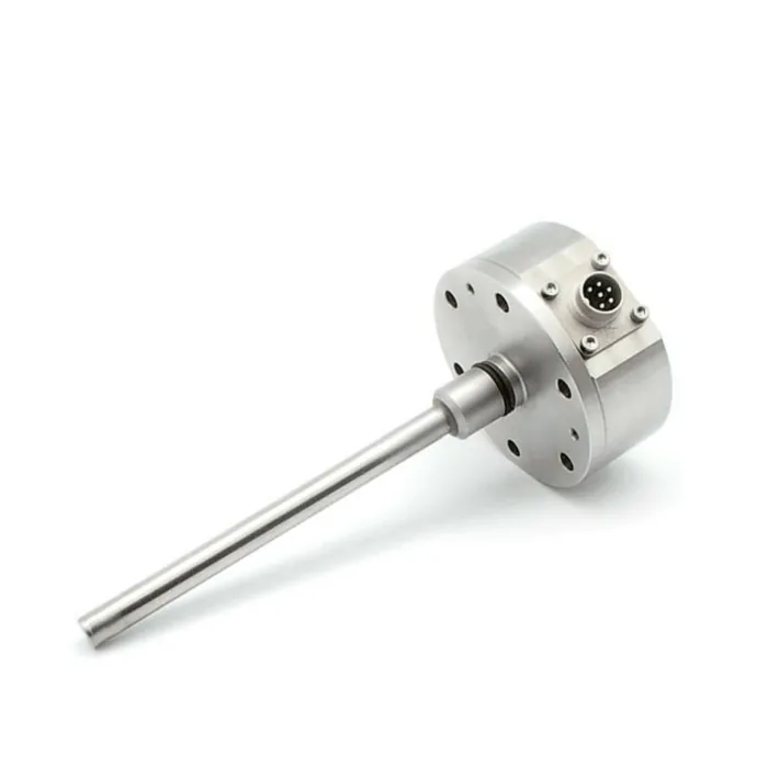
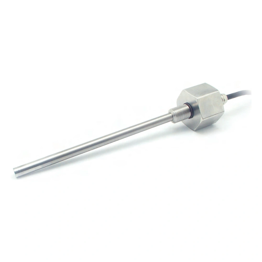
Series 13T magnetostrictive displacement sensor
Analog voltage/current or CANopen / SAE J1939, M18x1.5, 75-450 mm
The 13T is the mobile hydraulic model in Series 13, available with either an analog output (voltage or current) or a CANopen / SAE J1939 bus output. It is rated to 25g vibration and 100g shock, IP68 (IP69K when installed in-cylinder with an M12 connector), with a 75-450 mm stroke and ±0.10 mm resolution up to 500 mm. The bus version carries the protocol stack inside the sensor, so the 5-pin M12 delivers position directly.
Product Overview
The 13T mounts inside hydraulic cylinders with limited head space: M18x1.5 thread, Ø10 mm rod, damping zone selectable at 60 mm or 36.5 mm, minimum bore of 12.7 mm.
Two output types are available: analog (voltage or current on a 4-pin M12 A-coded connector) and bus (CANopen or SAE J1939 on a 5-pin M12 A-coded connector). The mechanical construction is identical, so the choice follows the control system.
The bus version has both protocol stacks built in, baud rate configurable from 10 kBit/s to 1 Mbit/s in eight steps, and Node-ID set as CANopen (01 to 7F) or SAE J1939 (01 to FD). It does not consume an analog input channel on the controller.
Three connection types are offered: pigtail, M12 connector and integral PUR shielded cable. The analog version is rated 350 bar (600 bar peak), the bus version 350 bar (530 bar peak).
The 13T covers 75 to 450 mm, the short-stroke end of the range. Series 13 also includes long-stroke versions from 50 to 2500 mm, so the choice follows the actual cylinder stroke rather than the other way round.
Operating Principle
The 13T uses the magnetostrictive measuring principle: a current pulse in the waveguide creates a circular magnetic field, and where it meets the permanent-magnet field of the position magnet an instantaneous strain wave is generated and travels along the waveguide. The electronics time the interval between the current pulse and the arriving wave and convert it to the absolute magnet position. The analog version outputs that position as a voltage or current; the bus version has the built-in protocol stack encode it as CANopen or SAE J1939 frames straight out of the M12 connector.
Typical Applications
Technical Specifications
| Measuring Range | 75 ~ 450 mm (25 mm increments) |
|---|---|
| Output Signal | Analog voltage/current, or CANopen / SAE J1939 (two options) |
| Resolution | <500mm ±0.10mm, 700mm ±0.18mm, 1000mm ±0.24mm, 1250mm ±0.30mm, 1750mm ±0.42mm |
| Repeatability | < ±0.005% of full scale |
| Non-Linearity | < ±0.04% of full scale (min. ±100 µm in the 60 mm damping zone); < ±0.08% (36.5 mm damping zone) |
| Supply Voltage | +12 Vdc / +24 Vdc |
| Input Protection | Reverse polarity protection to -30 Vdc, overvoltage protection to 36 Vdc |
| Power Consumption | 1 W |
| Dielectric Strength | 500 Vdc (DC ground to machine ground) |
| Operating Temperature | -40 °C to +85 °C, 90% humidity, non-condensing |
| Protection Class | IP68 (up to IP69K with an M12x1 connector when installed in-cylinder) |
| Vibration Resistance | 25g / 10~2000Hz (IEC 68-2-6) |
| Shock Resistance | 100 g single shock (IEC 68-2-27) |
| EMC Compliance | Emission EN 61000-6-3, immunity EN 61000-6-2, EN 61000-4-2/3/4/6 |
| Pressure Rating | Analog version 350 bar / 600 bar peak; bus version 350 bar / 530 bar peak |
| Housing Material | Stainless steel |
| Connector | 4-pin M12 A-coded (analog) / 5-pin M12 A-coded (bus); pigtail and integral PUR shielded cable also available |
Models and Output Signals
Dimensions and Wiring Diagrams
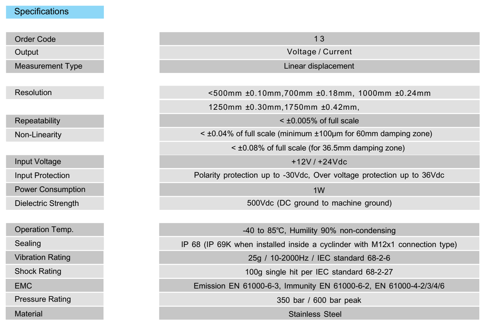
13T analog output technical specification table
13T analog output version: voltage or current output, stroke 75 to 450 mm, pressure rating 350 / 600 bar, IP68 / IP69K.
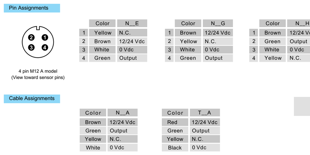
13T analog wiring diagram (4-pin M12 A-coded)
Pin assignment for the 4-pin M12 A-coded connector and cable colour codes for the N__E, N__G, N__H, N__A and T__A connection types.
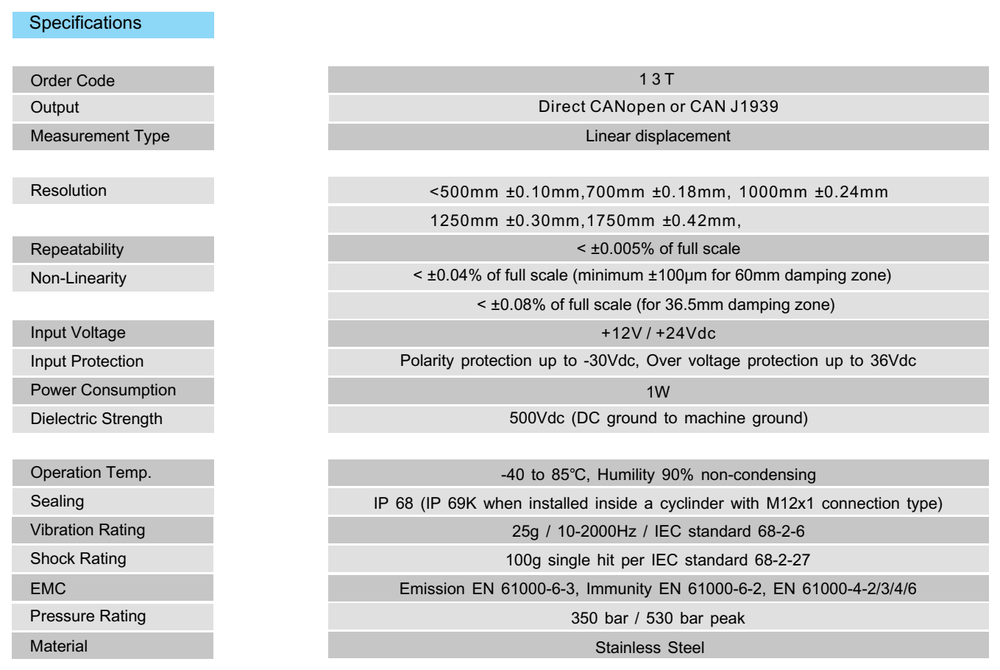
13T CANopen / J1939 output technical specification table
13T bus output version: direct CANopen or SAE J1939, stroke 75 to 450 mm, pressure rating 350 / 530 bar, IP68 / IP69K.
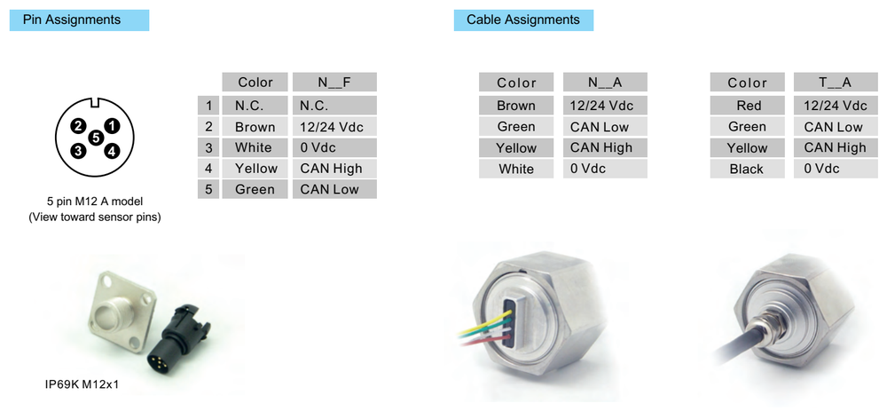
13T bus wiring diagram (5-pin M12 A-coded)
Pin assignment for the 5-pin M12 A-coded connector and cable colour codes for the N__F, N__A and T__A connection types.
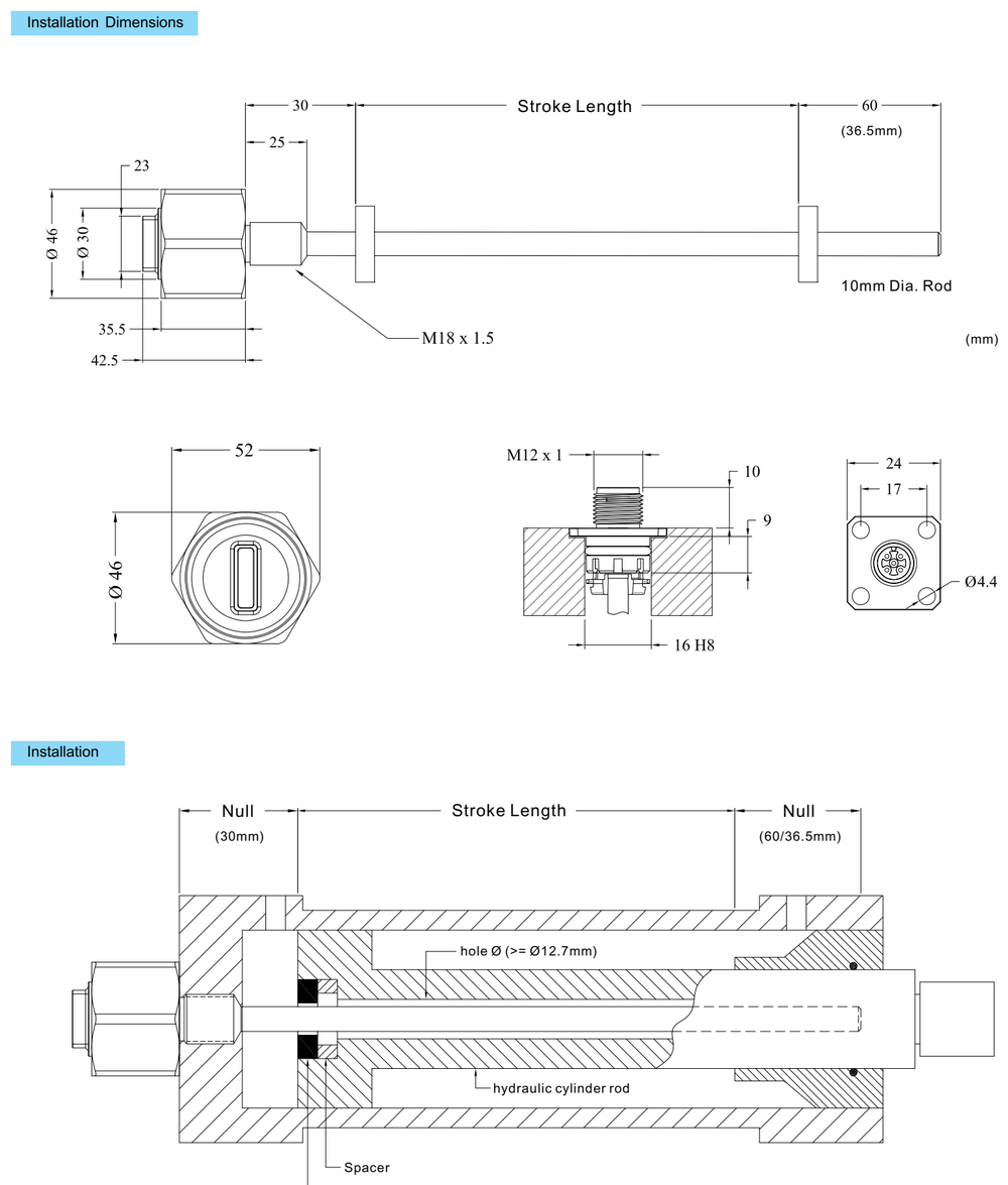
13T installation dimensions and in-cylinder mounting diagram
Installation dimensions: M18x1.5 thread, Ø10 mm rod, minimum bore 12.7 mm, spacer and ring magnet position.
Installation Precautions
- Fix the position magnet with a non-ferromagnetic circlip; ferromagnetic materials affect measuring accuracy.
- Minimum bore for a 10 mm rod is 13.5 mm, so that a sufficient mounting clearance remains.
- Leave at least 3 mm between the rod end and the bottom of the bore at full retraction, otherwise the sensing element can be damaged by mechanical impact.
- The mounting face must be flat and parallel to the cylinder axis; an offset face puts bending load on the sensor.
- Rated IP68 to IP69K, the sensor withstands high-pressure washdown and short immersion, but the electrical connector still has to be locked and sealed properly.
- Rated 25g vibration and 100g shock, the sensor should still be mounted so that its body cannot strike hard structures.
- On the analog version, route the signal cable away from battery and starter cables to limit electromagnetic interference and voltage drop.
- On the bus version, the baud rate must match the master (10 kBit/s to 1 Mbit/s) and the Node-ID must be unique on the segment: CANopen 01 to 7F, SAE J1939 01 to FD.
- Route CAN_H and CAN_L as a shielded twisted pair with the shield grounded at one point; wiring must follow 12 V / 24 V vehicle practice, including reverse polarity protection and surge suppression.
Pricing Notes
Series 13T is priced according to stroke, output type (analog voltage, analog current, CANopen or SAE J1939), connection type (pigtail, M12 connector or integral PUR shielded cable), damping zone length and magnet specification. The bus version costs slightly more than the analog version because of the built-in protocol stack.