
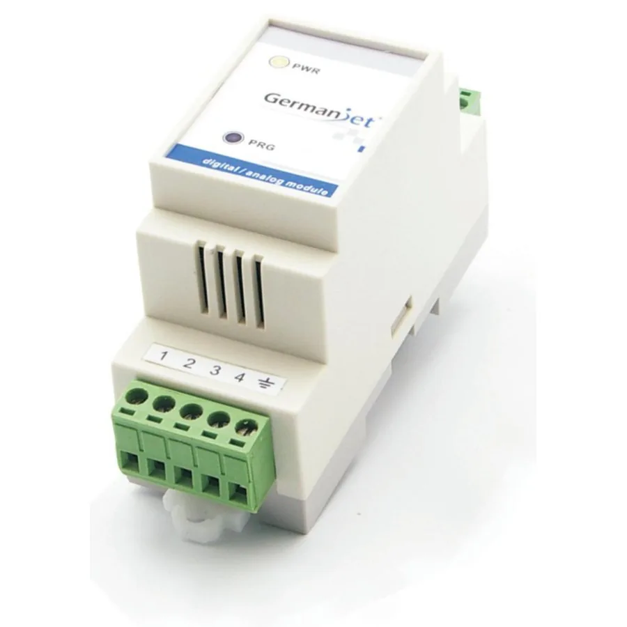
Digital/Analog (D/A) Conversion Module
Digital/analog (D/A) module for Start/Stop scales, 0-10V output, online programmable
The Germanjet Digital/Analog (D/A) Conversion Module (DAM) is mainly used with 1830 digital scales that provide a Start/Stop signal output, and is designed for environments with heavy interference. In day-to-day operation, analog signal transmission over distance is easily disturbed: cable quality, nearby equipment and the wiring environment all affect the analog signal. The scale outputs real-time displacement data as a Start/Stop digital pulse train, which is sent to the module installed in the control cabinet, which decodes it and converts it into a 0-10V voltage for the standard analog input of the controller. The module contains a dedicated 24V filtering and voltage-regulating system, providing a complete power supply solution for the measurement and removing the unstable readings caused by sharing a 24V supply on the machine. This approach requires no changes to existing equipment configuration, control computer or wiring, and the resulting displacement readings match the effect of a fieldbus solution.
Product Overview
The Germanjet Digital/Analog (D/A) Conversion Module (DAM) is a signal conversion module used together with 1830 digital scales that provide a Start/Stop signal output. The scale transmits real-time displacement data in digital format to the module installed in the control cabinet, which decodes it and converts it into a 0-10V voltage for the controller standard analog input.
The module contains a dedicated 24V filtering and voltage-regulating system, providing the most complete power supply solution for displacement measurement and removing the unstable readings caused by sharing a 24V supply on the machine. This approach requires no changes to existing equipment configuration, control computer or wiring, and the resulting displacement readings match the effect of a fieldbus solution.
The module is designed for environments with heavy interference: analog signal transmission is easily disturbed, and cable quality, nearby equipment and the wiring environment all have a major effect on it. The DAM module moves the conversion into the control cabinet and transmits the raw signal digitally, avoiding the interference of long analog runs at the source.
The module offers a simple zero and end point setting function. Simply move the magnet to the required zero and end positions and use the PRG key to complete the setting on site; the module can also provide this function for single-magnet output sensors. The module LED shows a flame symbol when there is no power supply, lights up during normal operation, and indicates programming modes and error states with different flash frequencies.
Operating Principle
The digital scale outputs displacement data as a Start/Stop digital pulse train. The DAM module receives and decodes it, then converts the displacement into a standard 0-10V analog voltage through a 16-bit D/A converter. A dedicated 24V filtering and voltage-regulating system provides a complete power supply for the measurement. The start and end output voltages of the displacement sensor can be programmed online: the zero and end points are calibrated on site with the PRG key, with no need to return the unit to the factory. The module also provides a control-computer alarm program: if it detects no displacement magnet, a broken connection between sensor and module, a sensor fault, or a problem at the module input interface, it immediately outputs 10V as an alarm signal that the control computer can use as a fault trigger.
Typical Applications
Technical Specifications
| Order number | 1800 951 021 |
|---|---|
| Output | Voltage 0-10V output |
| Input | Start / Stop digital pulse |
| Measured data | Linear displacement |
| Online programming | Start and end output voltages of the displacement sensor, programmable online |
| Resolution | 16-bit D/A, 0.0015% (minimum 1 μm) |
| Repeatability | Full scale < ±0.001% (minimum ±2.5 μm) |
| Non-linearity | Full scale < ±0.01% (minimum ±40 μm) |
| Update time | 0.5 ms up to 1200 mm / 1.0 ms up to 2400 mm / 2.0 ms up to 4800 mm / 5.0 ms up to 7600 mm |
| Supply voltage | +24 Vdc (20.4 – 28.8 Vdc) |
| Input protection | Polarity protection to −30 Vdc, overvoltage protection to 36 Vdc |
| Current consumption | 100 mA (depending on range) |
| Dielectric strength | 500 Vdc (DC ground to machine earth) |
| Operating temperature | 0 – 55 °C, non-condensing |
| EMC testing | Emission EN61000-6-3, immunity EN61000-6-2, EN61000-4-2/3/4/6 |
| Weight | 0.25 kg |
| Dimensions | 36 × 90 × 58 mm (W × H × D) |
Models and Output Signals
Dimensions and Wiring Diagrams
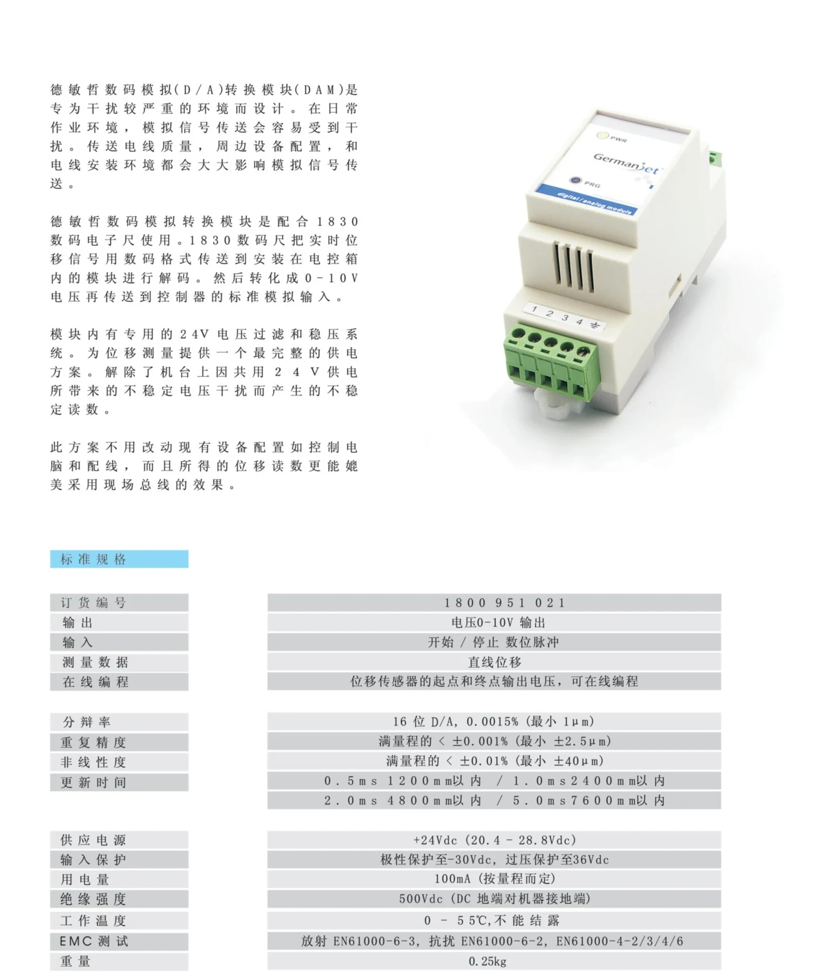
Digital/analog (D/A) conversion module - overview and specifications
Product overview, module photo and standard specification table (D/A accuracy, supply, EMC and all parameters)
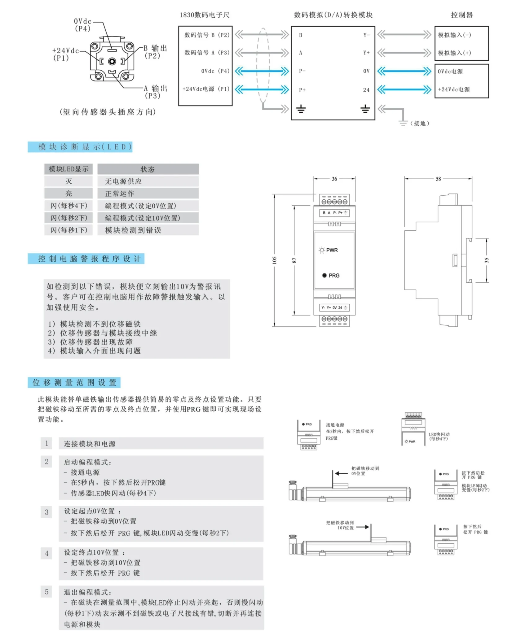
Digital/analog (D/A) conversion module - wiring diagram and dimensions
Wiring diagram (1830 digital scale to module to controller), diagnostic LED indication, control-computer alarm program design, outline dimensions and 5-step PRG key programming
Installation Precautions
- This module must be used with 1830 digital scales that provide a Start/Stop signal output; it cannot perform displacement measurement on its own.
- Wiring (looking at the sensor head socket): sensor socket — P1 = +24 Vdc supply / P2 = B output (digital signal B) / P3 = A output (digital signal A) / P4 = 0 Vdc; module terminals — A = digital signal A / B = digital signal B / P+ = +24 Vdc supply / P− = 0 Vdc; output side Y+ = analog input (+) / Y− = analog input (−); 24 = +24 Vdc supply / 0V = 0 Vdc supply.
- Supply is +24 Vdc (20.4 – 28.8 Vdc), polarity protection to −30 Vdc, overvoltage protection to 36 Vdc. Do not reverse or exceed these limits.
- The module contains a dedicated 24V filtering and voltage-regulating system. When the machine shares a 24V supply, confirm the voltage is stable to avoid interference and unstable readings.
- Operating temperature 0 – 55 °C, non-condensing. Install inside the control cabinet, away from direct oil mist, moisture and metal dust.
- Setting the measuring range: (1) connect the module and power supply; (2) start programming mode — power on, then press and release the PRG key within 5 seconds; the sensor LED flashes (4 times per second); (3) set the 0V start position — move the magnet to the 0V position, then press and release the PRG key; the module LED flashes more slowly (2 times per second); (4) set the 10V end position — move the magnet to the 10V position, then press and release the PRG key; (5) exit programming mode — with the magnet inside the measuring range the module LED stops flashing and lights up; a slow flash (1 per second) means no magnet is detected or the scale wiring is wrong.
- Module LED states: flame = no power supply; on = normal operation; 4 flashes per second = programming mode (setting the 0V position); 2 per second = programming mode (setting the 10V position); 1 per second = module error detected.
- Control-computer alarm program: on detecting any of the following faults the module immediately outputs 10V as an alarm signal, which the control computer can use as a fault trigger to improve safety — (1) no displacement magnet detected by the module; (2) broken wiring between displacement sensor and module; (3) displacement sensor fault; (4) problem at the module input interface.
- Use the high-immunity dedicated cable (order number 1800 951 023) and avoid routing parallel to power cables.
Pricing Notes
The price of the digital/analog (D/A) conversion module depends on quantity and the cable supplied. Please provide the scale model, measuring range and controller analog input specification for a quotation.


