
Magnet Ring Installed Backwards: Symptoms and Correction
A magnet ring fitted the wrong way round is one of the most common installation errors and one of the easiest to misdiagnose. It rarely stops the sensor working. Instead the reading becomes slightly wrong: good over one part of the stroke, poor over another, or offset by a fixed amount. The first reaction on site is usually to suspect the electronics or interference. The actual cause sits in the magnet orientation.
Four symptoms you can see directly
Periodic error across the stroke. Move the magnet slowly and evenly; the deviation follows a wave pattern with a roughly constant spacing between peaks. This is coupling strength changing because the magnet field is not perpendicular to the rod axis.
Local jumps at one position. The value suddenly jumps tens of millimetres and returns, while the rest of the stroke is fine. Around that region the coupling is too weak for a clean echo and the timer latches onto the wrong waveform.
Fixed offset overall. Every reading is larger or smaller than actual by the same amount, with acceptable repeatability. Typically the effective sensing centre of a reversed magnet no longer coincides with the mechanical datum.
No output, or a frozen value. The severe case. The field points fully away from the rod, coupling drops below the threshold for a detectable torsional wave, and the output locks.
In the first three cases the temptation is to retune controller parameters. That treats the wrong layer. The sensor is not faulty; the field is oriented wrongly, and parameter changes only make the error less visible.
Two polarity checks without disassembly
Read the markings. Most magnet rings carry a chamfer, colour dot or engraved line marking the working face. The datasheet draws an arrow for field direction; that arrow points toward the electronics head. Where no mark is visible, orient the flat face toward the head, since ring magnets are usually polarised across the two end faces.
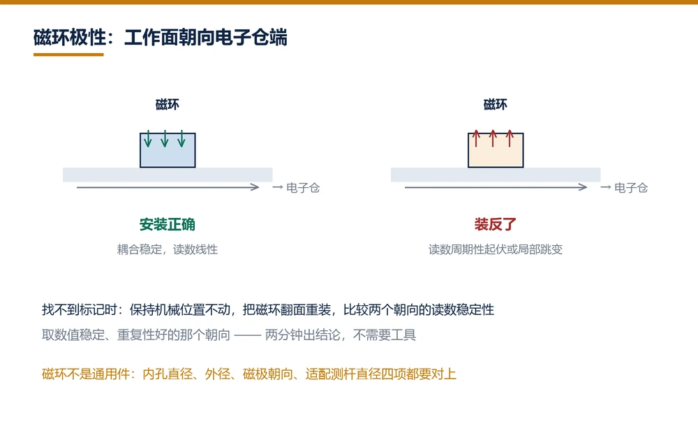
Flip and compare. The fastest practical test. Keep the mechanical position unchanged, remove the ring, turn it over, refit and read again. If the two orientations differ by more than the dead band magnitude, one of them is wrong. Keep the orientation that gives a stable, repeatable value. No tools required, two minutes to an answer.
Do the flip test with the axis stationary. Hot-swapping a magnet while the machine moves does not damage the sensor, but the reading jumps and invites a wrong conclusion.
Three details when correcting the position
Concentricity. Removing and refitting changes alignment. The radial clearance between ring bore and rod has a working range: too much weakens coupling, too little causes rubbing. Slide the ring through the full stroke by hand and feel for drag.
Axial fixing. The ring must not float on the rod. It is normally rigidly connected to the moving part, and a loose link shows up as hysteresis. On refitting, confirm the fastener has a locking feature: spring washer, thread locking compound, either is fine.
Nearby ferrous parts. Clamps, bolts and guards made of steel distort the field. If a small deviation survives reorientation, move ferrous parts at least 20 mm away and retest. This step clears many "corrected but still inaccurate" cases.
Confirming a replacement magnet matches
Magnet rings are available as spare parts, but bore diameter, outer diameter, pole orientation and field strength differ between series. Mixing them produces parts that fit but read incorrectly. Check four values: bore diameter, outer diameter, pole orientation, and the rod diameter the ring is matched to. Measure the first two, read the third from the marking, and confirm the fourth against the datasheet.
Where a non-standard ring is used, the first parameter to degrade is usually repeatability rather than linearity: returning to the same position several times gives different readings. Run a three-point return test, five passes per point, and compare spread against the rated repeatability.
A magnet ring for a magnetostrictive position sensor is not a commodity part the way an O-ring or a bolt is. Stock it by model number rather than by dimension, since rings of identical size with different pole orientation are common.
Frequently Asked Questions
Q: What are the symptoms of a magnet fitted backwards
Four: periodic error across the stroke, local jumps at one position, a fixed overall offset, or in severe cases no output at all. The first three are often mistaken for accuracy problems or interference when the field orientation is the actual cause.
Q: How can I check magnet polarity without taking the sensor apart
Read the chamfer, colour dot or engraved line marking the working face toward the head. If no mark exists, hold the axis stationary, flip the ring over, refit and compare readings. Keep the orientation that is stable and repeatable.
Q: Can a magnet ring be bought separately
Yes. A non-original ring will fit but may read incorrectly, so confirm bore diameter, outer diameter, pole orientation and matching rod diameter. Mixed rings usually show degraded repeatability first, detectable with a three-point return test.
Q: Will a reversed magnet damage the sensor
It does not directly damage the electronics or the waveguide. However, with weak coupling the ring can tilt during operation and score the rod surface, which permanently degrades measurement over that section. That is indirect damage.
Related Products
Related Applications

Multi-Industry Application Cases for Magnetostrictive Displacement Sensors
View Details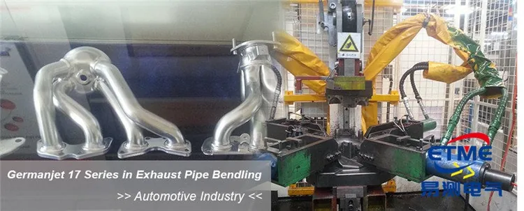
Series 16 Hydraulic Rod Magnetostrictive Displacement Sensor Application Cases
View Details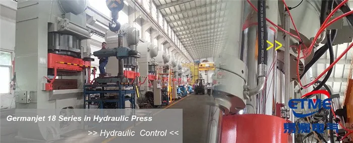
Series 18 Profile Magnetostrictive Displacement Sensor Application Cases
View DetailsWhatever the question above, it comes back to the same device.magnetostrictive displacement sensorThe product range lists every series by stroke, mounting style and output interface, which is the quickest way into a selection.
← Back to News