
What Happens When a Magnetostrictive Sensor Is Overstroked
On a datasheet, overstroke is a number. On site it is a specific failure mode, and the phrase covers three situations that behave differently: the magnet entering the dead band at either end, the magnet running past the head end and off the rod, and the magnet living permanently against a boundary. Telling them apart shortens diagnosis considerably.
Both ends of the stroke have a dead band
A sensor rated at 1000 mm has a usable measuring span, with a dead band at each end. The exact size depends on the model and must be read from the datasheet rather than assumed to be zero. The dead band exists because field coupling between magnet and wire is incomplete near the terminations: at the head end the housing obstructs it, at the far end the wire is anchored.
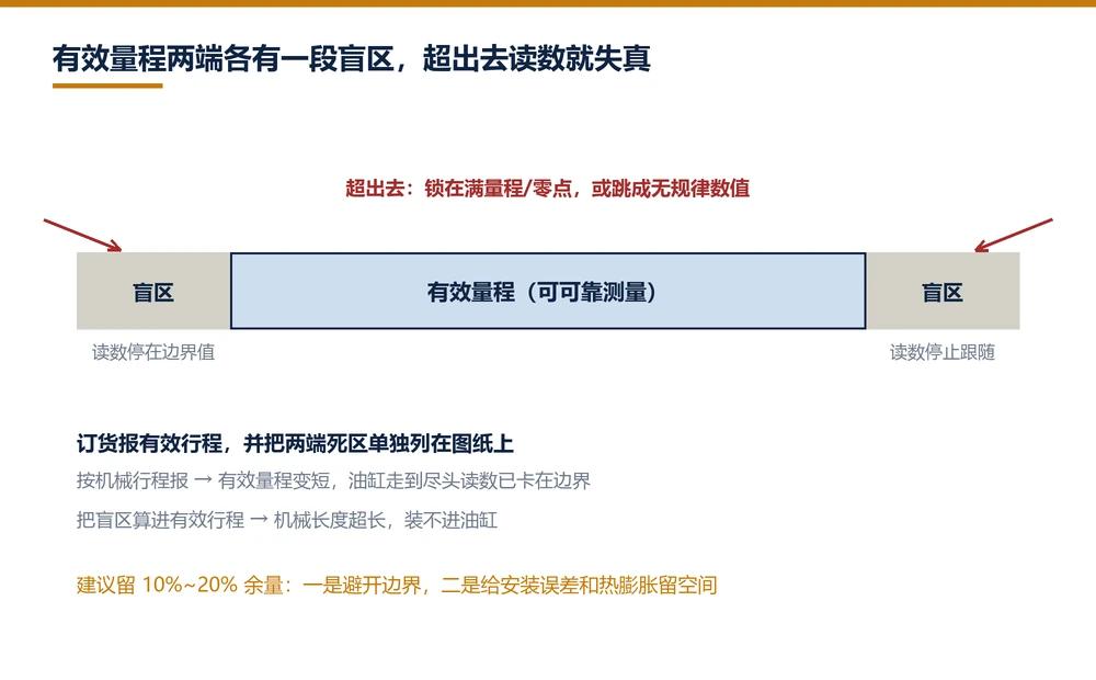
Folding the dead band into the stroke figure is the most common ordering error. A customer asks for 1000 mm, receives a sensor whose mechanical length exceeds 1000 mm, and cannot fit it into the cylinder. Ordering by mechanical length instead leaves a shorter usable span, so the reading reaches the boundary before the cylinder bottoms out. Specify effective stroke and confirm dead band separately.
Case one: the magnet enters a dead band
Inside the dead band the reading stops tracking and stalls near a boundary value or begins to jitter. The controller sees position that does not follow the command; if a tolerance check exists, it raises an out-of-range fault, otherwise the axis shows velocity loop oscillation at the end of travel.
This case is recoverable. Move the magnet back into the measuring span and the reading returns. The risk appears with repetition: pushing into the dead band flexes the radial gap between magnet and rod, and over time that gap opens, so readings become noisy even inside the valid span.
Case two: the magnet leaves the rod
When the magnet passes the head end or travels beyond the far anchor, readings take one of two extremes: locked at full scale or zero, or jumping to unrelated values. The first is a timeout value with no valid echo. The second is a stray echo accepted as valid.
This is more damaging than entering a dead band. If the magnet is pushed back on with the wrong attitude, it can score the rod surface. Wall thickness is limited, and a scored section couples poorly, which shows up as unstable readings in one narrow band of travel. That signature is often an old overstroke incident, easily misread as an electronics fault.
Case three: running permanently against the boundary
The least visible case. The mechanical design uses the full sensor span, so the magnet only ever moves within a few tens of millimetres at one end. Readings look correct, but only a short section of wire participates, torsional reflections near the anchor are stronger, and continuous stress in that region accelerates fatigue.
Detection is straightforward: pull the position history from the controller. If the value oscillates at high frequency within a narrow window, this is the pattern. The remedy is in selection, not service: leave margin.
Four preventive actions
Leave 10 to 20 percent margin. For a 1000 mm machine stroke, specify 1200 mm. The extra cost is trivial against unplanned downtime, and the magnet stops living at the boundary so the wire sees more uniform loading.
Specify effective stroke and confirm dead bands. List machine stroke, required measuring span and both dead bands separately on the drawing. For rod-style sensors inside cylinders, check the end cap bore depth as well; an insufficient bore leaves the sensor standing off, which creates overstroke by design.
Add a software limit. Set position limits 5 mm inside the effective span so the axis decelerates and stops before reaching the mechanical stop. It costs nothing and prevents most overstroke events.
Keep a mechanical limit. Hydraulic circuits should limit piston travel with switches or stops. A sensor is a measuring device, not a limit device; where it becomes the only limit, failure is a matter of time.
Receiving inspection check
Before installation, push the magnet slowly from one end to the other while watching the reading. Inside the effective span the value should change continuously and monotonically; at each end it flattens or starts to jitter. Note both transition points and compare with the datasheet dead bands. A deviation beyond 10 mm deserves a question to the supplier.
Also power cycle the sensor: an absolute-output unit should return to the same reading. A shift after power cycling points to a reference problem in the electronics, separate from overstroke, but it needs settling before the sensor goes on the machine.
Frequently Asked Questions
Q: Does running past the rated stroke damage the sensor
It depends how. Briefly entering a dead band stalls the reading but recovers once the magnet returns. Leaving the rod or running permanently against the end stop wears the rod surface and accelerates waveguide fatigue, which is irreversible.
Q: What does an overstroked sensor read
Three patterns: stalled near a boundary value with possible jitter in a dead band; locked at full scale or zero, or jumping to unrelated values, after the magnet leaves the rod; normal-looking values when the magnet simply runs permanently against a boundary.
Q: How much stroke margin should be left
10 to 20 percent. A machine with 1000 mm of travel should use a 1200 mm sensor. Margin keeps the magnet away from the boundary, spreads waveguide loading, and covers installation tolerance and thermal expansion.
Q: Should I order by mechanical stroke or effective stroke
Effective stroke. Dead bands at each end vary by model and must be confirmed separately. Including them makes the mechanical length too long for the mounting space; ordering by mechanical length shortens usable span so the reading hits the boundary early.
Related Products
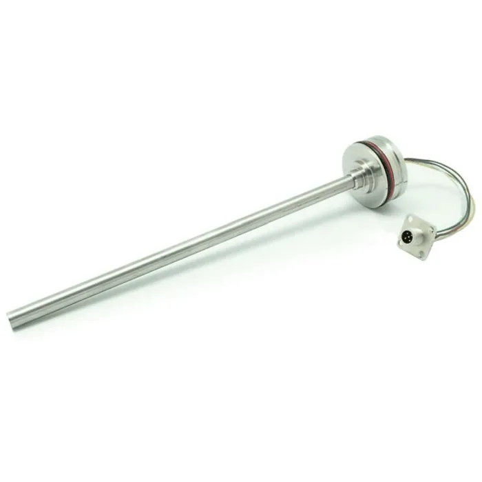
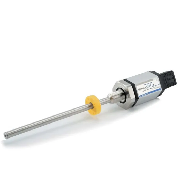



Whatever the question above, it comes back to the same device.magnetostrictive displacement sensorThe product range lists every series by stroke, mounting style and output interface, which is the quickest way into a selection.
← Back to News