
Germanjet CANopen Sensor Master: Command Bytes and States
Wiring a CANopen sensor into a PLC is mostly filling in a node number and importing an EDS; the position value then shows up in a tag table. Move to a custom board and all of that disappears: you receive the PDOs yourself, run the state machine yourself, and assemble every parameter into eight bytes by hand.
The application notes the factory supplies are written from the PLC side and read like instructions for one brand of controller. The frames are not brand-specific, though. The same eight bytes leave the PLC and leave a microcontroller identically. Pull the frames out of those notes, add the object dictionary, and what is left is a protocol you can code against.
One thing to settle first. Every index below is specific to the Germanjet 194 series, the CANopen version of Series 19.CANopen is a standard; the object dictionary is not. On another vendor's CANopen displacement sensor, 0x2010 may not be the baud rate, 0x300B may not be the node address, and 0x6020 may not hold position at all. Within the same brand and series the indices carry over; across brands they do not. The authority is the vendor's EDS file, not a generic table found online.
Confirm which device you have, do not guess
Copy the identity parameters down before wiring anything. They are the fixed values in the EDS, and they are also the credentials LSS uses to find the device.
- Vendor 0x40, product code 0x43333034.Read as ASCII that is "C304", which is where the model number comes from.
- Device type 0x1000 = 0x0A0196.The low word 0x0196 is 406, the CiA DS406 encoder profile; the high nibble 0x0A marks a multi-sensor interface, which is why one device can carry several magnets.
- Profile version 0x6507 = 3.1, followed by a manufacturer software version of 4.01.
- Node-ID ships as 127.The baud rate is set at order time and printed on the label.
The EDS file itself is not used in bare-metal development, only by configuration tools. Its object dictionary, however, has to serve as the parameter table: which index is writable, which is read-only, how wide the data type is. One wrong byte in a length field and the whole configuration is rejected. What DS406 settles covers the boundary of the profile; this article covers sending the frames.
SDO: one command byte decides how many bytes you write
An SDO is a fixed 8-byte frame: byte 0 is the command, bytes 1–2 the index (low byte first), byte 3 the sub-index, bytes 4–7 the data. The command byte determines how many of those data bytes are used, and this is where implementations usually go wrong.
| Command | Meaning | Data bytes |
|---|---|---|
| 0x2F | Write, 1 byte valid | 1 |
| 0x2B | Write, 2 bytes valid | 2 |
| 0x27 | Write, 3 bytes valid | 3 |
| 0x23 | Write, 4 bytes valid | 4 |
| 0x40 | Read request, no data | 0 |
| 0x60 | Write acknowledged (from slave) | 0 |
| 0x43 / 0x47 / 0x4B / 0x4F | Read response with 4 / 3 / 2 / 1 bytes | 4 / 3 / 2 / 1 |
| 0x80 | Abort, bytes 4–7 carry the abort code | 4 |
A read looks like this: the master sends 40 0B 10 00 00 00 00 00 to read 0x100B sub 0, the current Node-ID, and the sensor answers 43 0B 10 00 7F 00 00 00, where 7F is 127. A write looks like 2F 10 20 00 E8 03 00 00, setting 0x2010 to 0x03E8, that is 1000 kbps. Note that E8 03 is low byte first, which reads as though 0x03E8 had been written backwards.
When the command byte disagrees with the declared type, the device answers with an abort.Writing a single byte with 0x2F to an index declared Unsigned32 is tolerated by some devices and rejected by others. Storing parameters is the messiest case: 0x1010 sub 1 is declared 32-bit, so the canonical form is 0x23 with the signature 73 61 76 65 ("save"), yet the application note in circulation uses 0x2F with a single byte. Both completed the store in their respective notes, so the device accepts either. Pick one and hard-code it — installations where saving keeps failing are usually toggling between the two.
Two routes when you do not know the Node-ID
The sensor came off a shelf with a worn label, or three identical units are on one bus and nobody knows which is which. There are two ways out.
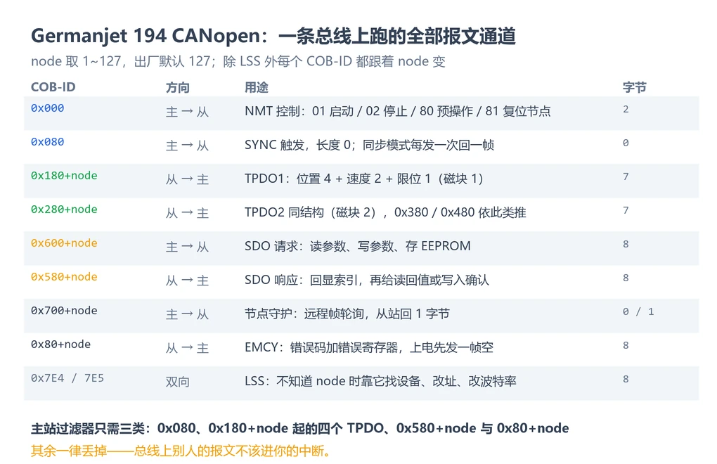
Infer it from EMCY.On power-up the sensor sends an empty EMCY whose COB-ID is 0x80 plus the node. Receiving 0xFF means 127; 0x9B means 0x1B, that is 27. This is the fastest route, and it only works when one sensor is on the bus or you are certain only one is.
Use LSS.0x7E5 is master-to-device and 0x7E4 is device-to-master, and neither changes with the node, which is exactly why they work when the node is unknown. Four steps: switch to configuration mode, confirm which unit you are talking to using the four identity values (vendor, product code, revision, serial number), write the new node or baud rate, then store and return to operation. With several identical units on one bus, the serial number is the discriminator — which is why it belongs in your notes from the first paragraph.
The exact LSS command bytes are in the CiA 301 LSS chapter and are wrapped by most master stacks, so there is no need to build them from scratch. What matters is knowing the service exists: the device already supports it (LSS_Supported = 1 in the EDS), and when a whole bus is silent with no known node, scanning with LSS beats unbolting sensors one at a time.
The published notes change node and baud rate through manufacturer objects instead — 0x300B for the node, 0x2010 for the baud rate — which requires that you already know the current node. With a known address that path is shorter; with an unknown one, use LSS. The two do not conflict.
Guarding: this device has no 0x1017
This is the step most often missed when moving off a PLC. The standard approach has the device act as a heartbeat producer on 0x700+node; the 194 object dictionary contains no 0x1017 entry. The EDS object list makes it plain: 0x100C guard time, 0x100D life-time factor and 0x100E guard COB-ID are all present, and the heartbeat producer entry simply is not there.
Node guarding is polled in the other direction: the master sends a remote frame to 0x700+node and the slave replies with one byte.Bit 7 toggles on every reply, bits 0–6 carry the NMT state (4 stopped, 5 operational, 127 pre-operational). That single byte tells you both that the device is alive and which state it is in.
- Timeout is guard time multiplied by the life-time factor. Writing zero disables guarding, and the slave will not complain that nobody is polling.
- Once guarding is enabled, poll it.A master that enables guarding and forgets the remote frame makes the slave conclude the link is dead; it raises EMCY
81 30(life guard error) and may stop sending PDOs. On site it looks like "it worked for a few seconds and then went quiet". - Do not copy a heartbeat configuration.Set up 0x1017 and wait for 0x700+node and you will wait for a timeout, because the device never sends it.
Four things the microcontroller has to supply
- Bit timing.500 kbps and 1 Mbps are the common settings; aim for a sample point of 80–87.5%. Compute the register values from the controller's bit-timing formula rather than copying another board — the same peripheral with a different crystal gives different numbers, and the symptom is "sometimes receives", which sends people chasing wiring.
- Acceptance filters.Let four groups through: 0x080, 0x180 through 0x480 plus node, 0x580+node and 0x80+node. Accept-all works on a bench; on a machine with a dozen devices it fills your interrupt with other people's traffic.
- Byte order and sign.Position is a 32-bit integer sent low byte first. Reassemble little-endian, and treat it as signed: with the zero point mid-stroke or the magnet travelling negative, the high bits are all ones and an unsigned read returns four billion-odd.
- Event timer and interrupt budget.0x1800 sub 5 is the event timer, 1 ms from the factory. Eight sensors at 1 ms is 8000 frames per second, which 500 kbps will not carry. Do the bus load arithmetic before choosing a period.
Converting position: three layers, do not hard-code one number
TPDO1 carries seven bytes: four of position, two of velocity, one of limit status. Position must be multiplied by the measuring step to become millimetres.
- 0x6005 sub 1 is the position measuring step in units of 0.001 µm; the default is 5000, that is 5 µm.
- 0x6501 is the step actually in use. Both it and 0x6005 are read-only; read them together at commissioning and compare.
- Conversion, using the published example:
03 83 00 00reassembles to 0x00008303, that is 33539; with a 0.005 mm step the position is 33539 × 0.005 = 167.695 mm.
0.005 mm is common, not universal. Different strokes and resolutions in the same series ship with different steps. Hard-coding the step rather than reading it produces a proportional error on the next batch — and because the error is uniform, it gets blamed on mechanics.
From power-up to a reading: the shortest path
Receive the EMCY on 0x80+node, send one NMT start frame (0x000, 01 00), and the sensor immediately returns one TPDO1. Whether it then runs synchronously or asynchronously depends on 0x1800 sub 2: 0 means transmit on SYNC, 254 means transmit on the event timer.
In synchronous mode each SYNC (0x080, length 0) makes all four magnets answer one frame each — stable order, identical time base. Asynchronous mode drops the SYNC but lets the timestamps of several devices drift apart. The full frame sequences for both modes are in the 19 series communication example; they are not repeated here.
Three things that stop a commissioning
- SDO answers, PDO does not.The device is in pre-operational. SDO configuration is allowed there but PDOs are not sent until an NMT start. The reverse is also true: SDO works in operational state, so "I can read parameters" does not mean "it is started".
- The node changed and the master lost it.Writing 0x300B changes the sensor's COB-IDs immediately; the master's receive IDs and filters have to move with it. The store command also has to go to the new address.
- Negative positions read absurdly.The value was treated as unsigned. An int32 with the high bit set becomes an astronomical number.
The complete frame sequences for node, baud rate and event timer are in changing CANopen parameters; the split between PDO and SDO and how to read an object dictionary is in the CANopen primer; fitting several magnets into eight bytes is in multi-magnet and the 8-byte limit. The 194 series and the CANbus integration module are the two pieces usually involved, and the selection boundary is in choosing a bus from the controller.
In one line
The frames are standard. What costs time is the state machine, the byte order and a handful of manufacturer-specific indices — align those three and a microcontroller master receives exactly the numbers a PLC does.
Frequently Asked Questions
Q: Can a microcontroller read the sensor without an EDS file?
Yes. The EDS is for configuration tools; bare-metal development only needs its content as a parameter table — the type, width and access rights of each index. What travels on the bus is the 8-byte frame, which is independent of the file. The dictionary itself cannot be guessed, though: a wrong length field earns an abort.
Q: Why is there no 0x700+node frame when a standard heartbeat is configured?
This device has no 0x1017 heartbeat producer in its object dictionary, only the three node-guarding objects 0x100C, 0x100D and 0x100E. Guarding runs the other way round: the master sends a remote frame and the slave answers with one byte. Configure heartbeat and you wait until the timeout.
Q: The position reads as a very large positive number — is the sensor faulty?
Check the sign first. Position is a 32-bit signed integer sent low byte first. Read as unsigned, a negative position has all high bits set and becomes four billion-odd. Declare an int32, reassemble little-endian, then multiply by the measuring step.
Q: How many 194 sensors fit on one bus?
The protocol allows nodes 1–127; the real limit is bus load. Each unit sends a 7-byte TPDO per event-timer period, so eight units at 1 ms is 8000 frames per second and 500 kbps cannot carry it. Do the arithmetic first: relaxing the period to 5–10 ms rarely affects control and frees most of the bandwidth.
Related Products
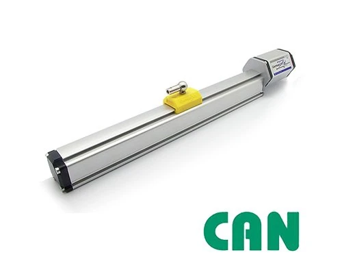
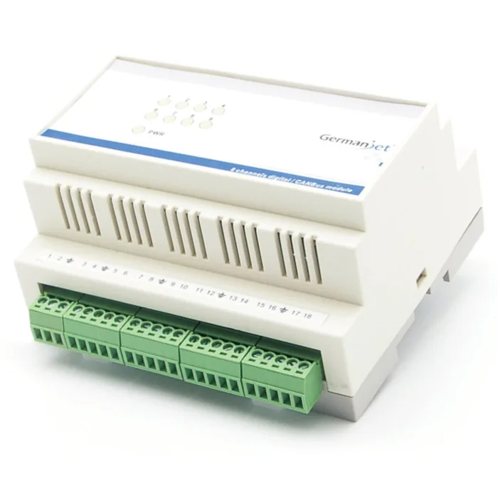


Whatever the question above, it comes back to the same device.magnetostrictive displacement sensorThe product range lists every series by stroke, mounting style and output interface, which is the quickest way into a selection.
← Back to News