
Signal and Power Cables: Separation and Shield Grounding
The note "do not run signal cable with power cable" has appeared on drawings for decades and is followed less often than written, because it states the prohibition without the numbers. What separation is enough, what to do at crossings, which end of the shield gets grounded. Without answers, installation comes down to judgement, and judgement usually produces the same intermittent fault it was meant to prevent.
Where the interference actually enters
Variable frequency drives, servo amplifiers and large contactors generate alternating magnetic fields around their cables. When signal and power cables run in parallel, capacitive and inductive coupling transfers voltage onto the analogue loop or swamps the differential signal on a bus.
The two output types behave differently. Analogue outputs (4-20 mA, 0-10 V) show continuous small-amplitude fluctuation. Digital bus outputs (SSI, CANopen, Profibus, EtherCAT) show occasional dropped frames, CRC errors and intermittent communication loss. Same root cause, completely different symptoms, so the diagnostic path differs.
Separation: how far is far enough
Best practice is separate tray or trunking. Where that is impossible, use a metal divider inside the same tray, bonded to earth. Typical separation is 200 mm or more for general power cables and 300 mm or more on the drive output side, where switching frequencies are high and currents are large.
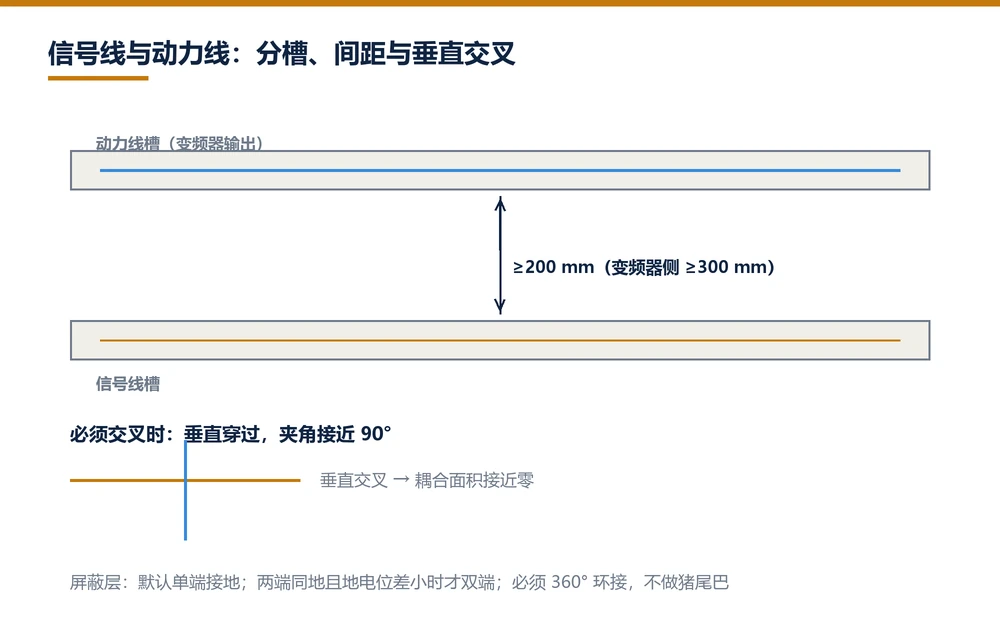
The detail that gets missed: separation applies to parallel runs. A short parallel section has limited effect. Ten metres of parallel run accumulates coupling even at the recommended distance, and no amount of shielding recovers it. In that case reroute; do not compensate.
Crossings
Cross at right angles. At 90 degrees the coupled area approaches zero, which is the cheapest possible remedy. A 45-degree crossing performs noticeably worse. Never route a crossing directly above the sensor head, which houses the most sensitive circuitry in the chain.
Shield grounding: one end or two
This is the most debated question on site and has no single answer; it depends on the grounding conditions at both ends.
Single-ended grounding is the default. Bond the shield at the controller only, leave the sensor end floating. This avoids circulating current driven by potential difference between grounds and is the safe choice on most industrial sites.
Double-ended grounding applies in two situations: both ends genuinely sit on the same earth with negligible potential difference, or high-frequency interference persists after single-ended bonding. The risk is a ground loop that injects the very noise it was meant to remove, so confirm earth resistance and potential difference first.
Two rules hold regardless: the shield is never used as signal ground, and the shield must be bonded 360 degrees rather than terminated with a pigtail. A pigtail is effectively no connection at high frequency.
Three-step verification after rerouting
Static observation. Machine stopped, sensor and controller powered, log the reading for ten minutes. Analogue fluctuation should stay below twice the rated resolution; bus error counters should be zero.
Drive start and stop. Cycle every drive on site through its normal sequence and watch for reading changes. This is the critical step: a quiet static reading does not mean a quiet dynamic one, since much interference appears only at specific switching frequencies.
Full stroke run. Traverse the complete stroke and compare readings taken at the same position on the way out and back. Under heavy interference those two will differ.
All three must pass. Stopping after the first step is the most common cause of a second service visit.
Two small items that matter
On a 4-20 mA loop, conductor size barely matters but termination quality does. A poorly crimped terminal or a loose screw adds contact resistance that varies with temperature, appearing as drift and sending people after a non-existent thermal problem.
On a bus, match conductor size to the impedance and length. CANopen expects 120 ohm twisted pair; SSI uses shielded twisted pair. Undersized conductors attenuate the signal and slow the rise time, so the link fails well short of the nominal distance. Cable selection has to be done together with baud rate and bus length, not on conductor size alone.
Frequently Asked Questions
Q: Can signal and power cables share the same tray
Not recommended. If they must share a tray, use a bonded metal divider and keep parallel runs at least 200 mm apart, 300 mm on drive output cables. Short parallel sections matter little; long ones accumulate coupling even at the recommended distance.
Q: How should signal and power cables cross
At right angles. At 90 degrees the coupled area approaches zero, which is the cheapest remedy. Avoid diagonal crossings and never cross directly over the sensor head, which houses the most sensitive circuitry.
Q: Should the cable shield be grounded at one end or both
Single-ended by default, bonded at the controller with the sensor end floating, to avoid circulating current. Use double-ended only when both ends share the same earth with negligible potential difference, or when high-frequency noise persists after single-ended bonding.
Q: How do I confirm interference is actually fixed
Three steps: log the reading for ten minutes with the machine stopped; cycle every drive through its normal sequence and watch for jumps; run the full stroke and compare readings at the same position on the way out and back. All three must pass.
Related Products
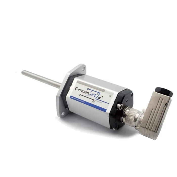
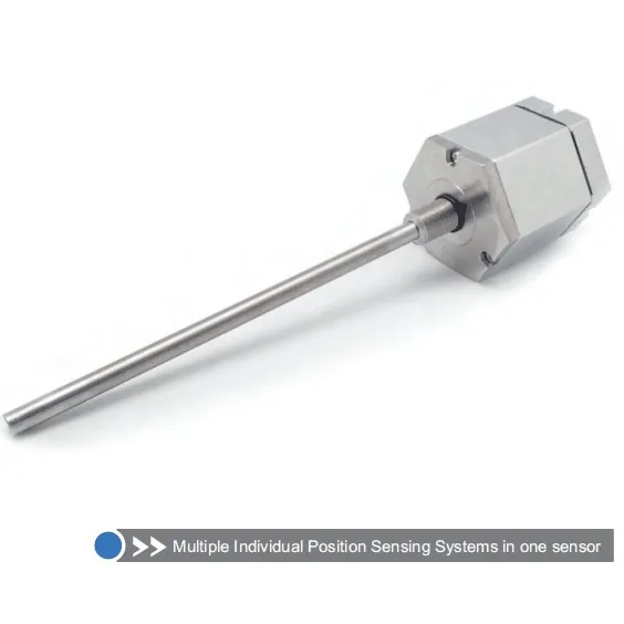
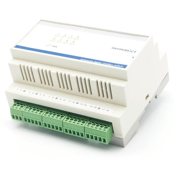
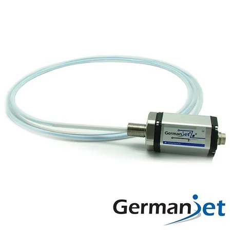
Whatever the question above, it comes back to the same device.magnetostrictive displacement sensorThe product range lists every series by stroke, mounting style and output interface, which is the quickest way into a selection.
← Back to News