
Laser Platform Backfill: Displacement Sensor for Shuttle and Z Axes
A magnetostrictive displacement sensor on laser cutting and welding platforms backfills, rather than replaces, the main motion axes. Those axes are normally closed-looped by servo motors with linear scales or encoders, and the sensor's role is to complement, not replace: it is used for shuttle-table positioning, Z-axis lift and focusing mechanisms, clamp and hold-down stroke, and position confirmation on welding positioners and fixtures. These mechanisms share long strokes, an environment of metal dust and spatter, and a requirement that position be restored immediately after a power loss — precisely the scope of non-contact absolute-position measurement.
Where displacement is measured on laser equipment
Typical measuring points fall into four classes: the shuttle table (long-stroke reciprocation; position determines load/unload docking accuracy), the Z-axis / focusing mechanism (short stroke, accuracy-critical, affecting focal position), clamping and hold-down (in-position confirmation and hold-down stroke), and positioners and fixtures (weld-attitude positioning). Z-axis focusing is the most demanding on resolution; a 1-5 μm grade is recommended. Long-stroke mechanisms such as shuttle tables are adequately served by a 20-50 μm grade. Resolution and accuracy are not the same concept; selection criteria are given in the three accuracy terms.
Measuring points and configuration
| Measuring point | Stroke character | Resolution grade | Key indicator | Recommended interface |
|---|---|---|---|---|
| Shuttle table | Long-stroke reciprocation | 20-50 μm | Absolute position, repeatable in-position | 4-20 mA / fieldbus |
| Z-axis / focusing | Short stroke, accuracy-critical | 1-5 μm | Repeatability, refresh rate | EtherCAT / SSI |
| Clamp / hold-down cylinder | Short stroke | 20-50 μm | Reliable in-position criterion | Analog |
| Positioner / fixture | Medium stroke | 10-20 μm | Spatter resistance, noise immunity | Fieldbus |
Metal dust and spatter: two site problems that must be dealt with
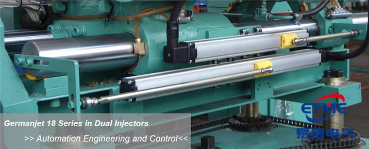
Metal dust from laser cutting is often magnetic; it is attracted by the position magnet and builds up on the magnet face. This is the most typical site pitfall in the industry: readings are normal at first, then after some weeks of running isolated position jumps appear. The remedy is to place the rod away from fume-extraction and chip-fall paths, fit a guard, and put “clean the magnet face” on the weekly maintenance list; a magnetostrictive displacement sensor that runs fine then jumps is usually dust on the ring. Spatter at welding stations will damage an exposed rod surface directly; a metal guard must be fitted, or the sensor must be mounted in-cylinder. A protection rating of IP67 or better is recommended; for what the ratings mean see what IP protection ratings really mean. For profile-type products see Series 18 profile type.
Electromagnetic environment: interference from the laser supply and welding current
When the laser supply, inverter welder and servo drives share a cabinet, the electromagnetic environment is severe. Large welding currents switching on and off in an instant can couple noticeable interference onto signal cables, appearing as reading jumps at the moment of cutting or arc strike. The countermeasures are three: run signal and power cables in separate trunking and keep them spaced; earth the screen at one end, choosing the control-cabinet side; and do not share a return path between the welding-circuit earth and the signal earth. For the principle and the difference between specification and site measurement see EMC; for the troubleshooting sequence see troubleshooting.
Connecting to the motion-control system
If the machine uses an EtherCAT architecture, bringing the displacement sensor in as a slave yields distributed-clock synchronisation: multi-axis data are sampled at the same instant, which is convenient for position comparison and coordinated control. See Series 197 EtherCAT and the configuration notes in the practical CANopen and EtherCAT guide. The selection framework for hydraulic clamping circuits is given in hydraulic cylinder position-control schemes. Displacement requirements for robot handling and load/unload coordination can be compared with industrial robots: seventh-axis and vertical-axis position.
Frequently Asked Questions
Q: What happens if the two sides of a gantry are not synchronised?
Twisting and joint mismatch result. The two axes must be sampled synchronously; asynchronous sampling produces false gap alarms in the high-speed section.
Q: How should the refresh rate be checked on a long stroke?
Torsion-wave propagation time is proportional to measuring range, so a long stroke responds more slowly. Confirm that the refresh rate is no lower than the control cycle; see the article on matching response time.
Q: How should a platform with high vibration be specified?
For vibrating stations specify Series 13, IP69K, 25 g vibration resistance; for dry-area positioning specify Series 18 profile type.
Related Products




Related Applications

Multi-Industry Application Cases for Magnetostrictive Displacement Sensors
View Details
Series 17 Hydraulic Cylinder Integrated Magnetostrictive Displacement Sensor Application Cases
View Details
Series 18 Profile Magnetostrictive Displacement Sensor Application Cases
View Details