
Take-Out Robot Three Axes: Strip-Axis Mould-Area Interlock
The positioning problem of an injection-molding take-out robot is, in essence, a balance between a high cycle rate and a cramped mould space: the faster the motion, the shorter the cycle, but the greater the risk of position error when entering the mould area. If position feedback on the three axes (traverse, strip, and up/down) relies only on the servo-motor encoder, belt elasticity, backlash and frame vibration are all invisible. Fitting a magnetostrictive displacement sensor that measures the actuator end directly yields absolute position, eliminates transmission error, and, on power-up, confirms without homing whether the arm is stopped inside the mould area.
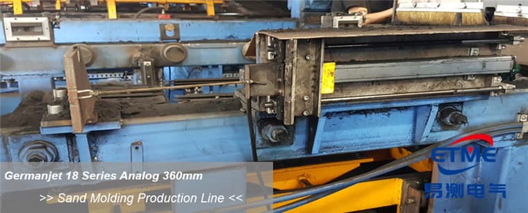
Different requirements on the three axes
The traverse axis has the longest stroke (along the machine); the concerns are absolute error at long range and refresh rate during high-speed motion. The strip axis reaches into the mould area to take the part; position error relates directly to mould-crash risk, so repeatability and the in-position criterion are the most critical. The up/down axis (Z-axis) has a medium stroke; the concern is reading stability during acceleration and deceleration. Of the three axes, at least the strip axis should have independent position feedback as one of the permits to enter the mould area, interlocked with the injection-molding machine’s platen-position signal. Measuring-point schemes on the machine side are given in injection molding: closing the loop on clamping force and shot volume.
Three-axis configuration
| Axis | Stroke order | Resolution grade | Primary indicator | Safety use |
|---|---|---|---|---|
| Traverse axis | Long stroke | 20-50 μm | Long-range error, refresh rate | Over-travel protection |
| Strip axis | Medium stroke | 5-20 μm | Repeatability, in-position criterion | Mould-area entry interlock |
| Up/down axis | Medium stroke | 10-20 μm | Stability under acceleration | Lowering limit |
| Sub-arm / flip | Short stroke | 20-50 μm | In-position confirmation | Attitude confirmation |
Refresh rate and lag at a high cycle rate
Take-out cycles are typically counted in seconds; position data in the high-speed section of the arm motion must be dense enough. Refresh rate lengthens as measuring range increases (about 0.5 ms to 5 ms depending on model and range). The long-stroke traverse axis in particular must be checked on this point, otherwise the judgement of the deceleration point shows an “overshoot then pull-back” behaviour; a long traverse axis whose refresh is too slow overshoots then pulls back at the deceleration point, so check range before cycle. The matching method is given in response time / refresh rate and the control cycle. On a fieldbus architecture, EtherCAT distributed clocks let the three axes be sampled at the same instant, which is convenient for trajectory checking. See Series 197 EtherCAT and the configuration in the practical fieldbus guide.
Installation and vibration: the most typical site pitfall on take-out robots
Take-out robots are lightweight. At high-speed start and stop the frame and beam exhibit elastic deformation and residual vibration. If the magnet bracket is not rigid enough, the reading fluctuates strongly with acceleration and deceleration, and this is easily misread as a sensor-accuracy problem. Lightweight high-speed arms leave residual vibration; the order of treatment should be: first stiffen the magnet bracket and shorten the cantilever, then suspect sensor accuracy. Mount the rod parallel to the direction of motion and leave allowance at both ends of the full stroke to stay clear of the dead zones (see effective range and dead zones). An injection-molding shop has oil mist and mould-release spray; a protection rating of IP65 or better is recommended (see IP protection ratings). For profile-type products see Series 18 profile type.
Common ground with robot external axes
A take-out robot and an industrial-robot seventh axis are highly consistent in “long-stroke linear positioning + absolute position + high cycle rate”. The same magnetostrictive displacement sensor principle serves both, and installation and synchronisation experience can be borrowed in both directions; see industrial robots: seventh-axis and vertical-axis position. The selection framework for hydraulically driven auxiliary clamp axes is given in why hydraulic cylinder position control uses magnetostrictive sensing.
Practical tips for engineers
- Series 19F front dead zone: 50 mm for strokes <8000 mm, 130 mm for strokes >8000 mm; deduct this when calculating the usable stroke at the selection stage.
- Overall sensor length tolerance is +8 mm for strokes <8000 mm, and +15/-5 mm for strokes >8000 mm; this tolerance does not affect the measuring stroke.
- Series 19F has a minimum stroke of 250 mm; specify another series for shorter strokes.
Frequently Asked Questions
Q: Why add linear displacement sensing to a take-out robot?
The encoder sees the motor end; backlash and compliance are invisible. Measuring the actuator end directly eliminates the error and removes homing.
Q: How is it interlocked with the injection-molding machine?
Confirm platen position before entering the mould area and use a displacement interlock to avoid interference; see the article on injection-molding take-out robots.
Q: How should a profile type be specified?
Specify Series 18 profile type in dry areas and Series 13, IP69K, at vibrating stations. Use absolute position so that homing is unnecessary.
Related Products



Related Applications

Multi-Industry Application Cases for Magnetostrictive Displacement Sensors
View Details
Series 17 Hydraulic Cylinder Integrated Magnetostrictive Displacement Sensor Application Cases
View Details
Series 18 Profile Magnetostrictive Displacement Sensor Application Cases
View Details