
Analog Output Calibration on a Magnetostrictive Sensor: Three Layers
A replacement sensor goes in. Same model, same mounting, same magnet. The position in the PLC is 3 mm short of where it used to be, and nobody touched the program. The first conclusion on site is usually "this gauge is off". What actually happened is that the new unit puts 4 mA at 3.94 mA and 20 mA at 19.9 mA, and the controller's scaling formula stretches that small offset into 3 mm over an 800 mm stroke.
Analog output calibration is not about making the sensor accurate. It is about putting three separate error layers back where they belong. Without that split, every adjustment is a guess about which layer you are actually moving.
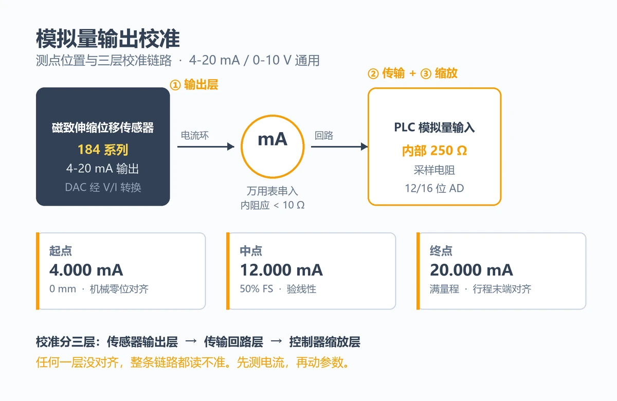
You are calibrating a loop, not a gauge
Between the sensor and the millimetre value in the PLC, the 4-20 mA signal passes three stages, and each one contributes error.
- Output layer.The sensor converts position to a digital value, then a DAC and a V/I stage turn it into current. Error here comes from DAC offset and gain, and every unit is calibrated at the factory (see factory calibration and dead-zone compensation). Replace the gauge, disturb the magnet, touch the programmer, and this layer is back to unaligned.
- Transmission layer.Cable resistance, contact resistance, the sampling resistor inside the analog input card and a sagging supply all make the current arriving at the card smaller than the current leaving the sensor. You cannot see this layer, you can only measure it.
- Scaling layer.The controller turns 4-20 mA into millimetres with a formula. The coefficients are written by a person; mistyped, copied from the previous stroke, or inherited from another machine, they leave no trace in the current but land entirely in the reading.
The three add up directly. 0.05% FS at the output, 0.1% in the loop and 0.2% in the scaling gives 0.35% FS — 3.5 mm on a one-metre stroke. That is exactly the size of error that looks wrong without pointing anywhere.
Measure current before touching a parameter
There is one entry point for deciding which layer is off: read the real current. Set the meter to mA and put it in series with the loop, not across it. Between the positive supply and the sensor, or between the sensor output and the PLC input, the same loop current flows.
- Range.mA, never the A range. A low-impedance current range does not have the resolution to show a 16 µA change.
- Meter burden.mA ranges run from a few ohms to tens of ohms and drop voltage in the loop. When the loop load is already near its limit, that burden pulls the current down and the reading reads low, which is how good sensors get condemned. A meter specified under 10 Ω is safe to insert; a 100 Ω meter needs load headroom.
- Load resistor.Analog input cards are commonly 250 Ω, where 20 mA is 5 V. Some are 500 Ω, some switch between 100 and 250 Ω. Check the setting before you measure, or the whole conversion is out by a factor of two.
Park the piston somewhere repeatable before you start — a mechanical hard stop is best, a clamped block works. Every number afterwards is compared against that point.
Two numbers to record: start current and span
Drive to the mechanical start, read the current, call it I₀. Drive to the end of stroke, keeping clear of the dead zone (see effective range and dead zones), read it, call it I₁.
- Start offset = I₀ − 4.000 mA, the zero error.
- Span = I₁ − I₀, nominally 16.000 mA. A span error is a gain error.
A realistic set of numbers: I₀ = 4.032 mA and I₁ = 19.884 mA. The zero sits 0.032 mA high, which is 0.2% FS. The span is 15.852 mA, 0.148 mA short of nominal, which is −0.93% FS. Pull the zero back to 4.000 mA on its own and the far end is still 0.148 mA low; the error starts in mid-stroke and grows toward the end.
Correct span to 16.000 mA first, then move the zero. Do it the other way and adjusting span drags the zero with it, which is the most common reason a calibration has to be done twice.
Zero and range: sensor side or controller side
Both ends can be adjusted, but they are not the same adjustment.
- Sensor side.Which mechanical position gives 4 mA and which gives 20 mA is fixed at order time on the analog models, and every unit is calibrated at the factory. To reset that scale on site, the 1700 951 018 programmer on the 19 series will do it: it sets the mechanical start to 4 mA and the end of stroke to 20 mA, changing the sensor's own output scale so the controller scaling stays as it is. Procedure in setting start and end with the programmer. Series 18 and Series 17 do not use that programmer; on those, the work is done in the controller — measure the current first, see whether the error sits in the offset or the span, then decide which end to move.
- Controller side.Leave the sensor alone and change the scaling coefficient and offset in the PLC. Use this path when only the analog card changed, when its range setting moved, or when the old coefficients were copied from a different gauge.
Do not adjust both. The classic failure is a fitter nudging the sensor while an engineer compensates in the PLC; both believe they are correct, and the next replacement starts from an unknown scale with nothing on paper to recover it.
Controller side: put the current into slope and datum
Once the current is measured and the controller is the side to adjust, it comes down to two coefficients. The arithmetic is identical to a voltage output; only the unit changes from volts to milliamps.
- Slope = actual travel ÷ (I₁ − I₀), in mm/mA.
- Datum = slope × I₀, in mm.
- Position = slope × I − datum.
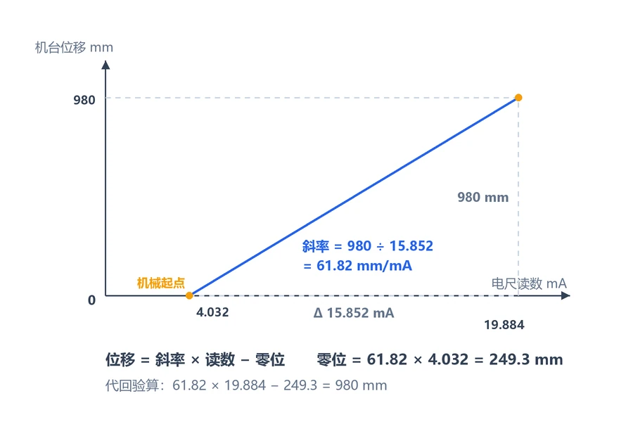
With the earlier numbers, taken from a Series 18 model 184 (4-20 mA) on a 1000 mm stroke — I₀ = 4.032 mA, I₁ = 19.884 mA across 980 mm of measured travel — the slope is 980 ÷ 15.852 = 61.82 mm/mA and the datum is 61.82 × 4.032 = 249.3 mm. Feeding I = 19.884 back through the third line gives 61.82 × 19.884 − 249.3 = 980 mm, which closes.
Do not use range ÷ 16 mA as the slope. That gives 61.25 mm/mA and leaves roughly 0.9% FS at the far end, about 9 mm on a 980 mm stroke, all of it coming from the 0.148 mA the span is short. Working from the two measured points folds that shortfall into the slope, which is why the reading then agrees.
There is also a form problem when entering the values. Some controllers want slope and datum as two coefficients; others want the endpoint form, 4 mA at the lower limit and 20 mA at the upper. The two are mathematically equivalent, and mixing them halves or doubles the travel — entering 61.82 in the upper-limit field doubles every reading.
For a voltage output the equations do not change: 4-20 mA across 250 Ω is 1-5 V, so only the unit moves, and a 0-10 V sensor uses the same two readings, one slope and one datum. The full derivation with the original worked example — 0.2 V, 9.5 V, 98 mm — is in zero calibration with a mechanical reference and two points; this article adds the current-side case only.
The midpoint is a check, not an adjustment
Two points define a straight line. Matching both ends does not mean the middle is right. The midpoint tests linearity; it is not a place to trim.
Move to the mechanical mid-stroke position and read the current. Nominal is 12.000 mA, measured against the actual span rather than as an arithmetic mean of 4 and 20. A midpoint deviation above 0.1% FS means this is not a simple offset and gain problem. The shape of the deviation tells you which:
- Ends good, middle off in one direction.The rod is bent by side load, or the bore and rod are not coaxial. Check alignment as in magnet eccentricity and misalignment.
- Ends off, middle good.The range was ordered too long, the machine never uses full stroke, and both ends sit outside the linear section.
- One band in the middle off.Usually mechanical: a step in the bore, the cushion entering, or the magnet passing a weld. See cushion at end of stroke.
Four field traps that waste a calibration
- Meter burden ignored.An A range or a high-burden meter in a 250 Ω loop drops more than 2 V at 20 mA, pulling the current into the low 19s. You then trim a perfectly good sensor and leave with the wrong conclusion written down.
- Calibration points inside the dead zone.Both ends of the effective range have tens of millimetres where the current stops moving or jumps. Setting the start point inside that band means using a number that does not change as your zero.
- Cold machine or hot machine, whichever came first.Oil going from 30 °C to 55 °C moves the rod by thermal expansion and the electronics by drift, together worth a fraction of a millimetre. Record the temperature at calibration; where the swing is large, measure cold and hot and record the difference.
- Current calibrated, controller not.The current is perfect and the scaling is stale, so the reading is still wrong. The last step is always the PLC watch table in millimetres, not the meter in milliamps.
What the calibration record has to contain
Raw currents, not the words "calibrated". That sheet is the only thing that lets the next person reproduce the scale.
| Point | Mechanical position | Measured | Nominal | Deviation | Result |
|---|---|---|---|---|---|
| Start | Piston at stop | 4.000 mA | 4.000 mA | 0 | Pass |
| Mid | 50% of stroke | 12.004 mA | 12.000 mA | +0.025% FS | Pass |
| End | 20 mm clear of dead zone | 19.996 mA | 20.000 mA | −0.025% FS | Pass |
Do not drop the notes column: oil temperature, meter burden, load resistor setting, and whether the sensor or the controller was adjusted. Those four lines save the next person from starting over.
Digital outputs skip this, but still need a zero
SSI, CANopen, EtherCAT and PROFINET send a digital position. There is no DAC, so there is no 4 mA and 20 mA gain and offset to chase. They need something else: mapping the mechanical start to a position value. The methods differ by protocol — see SSI timing and data bits and CANopen DSP406 configuration — but the principle is the same.
Choosing between output types is covered in 4-20 mA versus CANopen; two-, three- and four-wire analog wiring in wiring the two output types, with the Series 18 model 184 (4-20 mA) being the common choice for this kind of work. How often to calibrate, and when to send a unit away, is in calibration intervals and three decision lines.
The short version
Meter in series, start current for zero, span for gain, midpoint for linearity, controller watch table for millimetres. If all five still disagree, the problem is no longer electrical — go and look at the mechanics.
Frequently Asked Questions
Q: Can the 4-20 mA zero be set on the sensor itself?
Yes, but decide which layer you are changing. The 1700 951 018 field programmer on the 19 series sets the mechanical start to 4 mA, which changes the sensor's own output scale and leaves the controller coefficients untouched. Adjusting only the controller leaves the sensor scale as it was, so those coefficients stop applying the moment the gauge is replaced. Move both and you have no reference left.
Q: Why does the meter current differ from what the PLC calculates?
Two usual causes. Meter burden pulls the loop voltage down — tens of ohms is enough to lose a fraction of a milliamp at 20 mA. Or the internal sampling resistor is not the value you assumed, where 250 Ω and 500 Ω differ by a factor of two in the conversion. Measure at the supply end with the meter, then read the raw value with the meter removed, and compare both.
Q: Are calibration and adjustment the same thing?
In the field the words get mixed. Setting the correspondence between mechanical position and output — zero and full scale — has to be redone after a replacement or a re-install. Verifying and correcting an existing correspondence can be done with two or three points without touching the mechanics. Different intervals, different people, different tools.
Q: After changing the analog input card, does the sensor need recalibrating?
Not the sensor, but the card does. Sampling resistor, range setting and ADC resolution may all differ, so the old scaling no longer holds. Measure the actual current to confirm the sensor is unchanged, recompute the coefficients against the new card, and check the midpoint. Do not carry the old parameters over.
Related Products
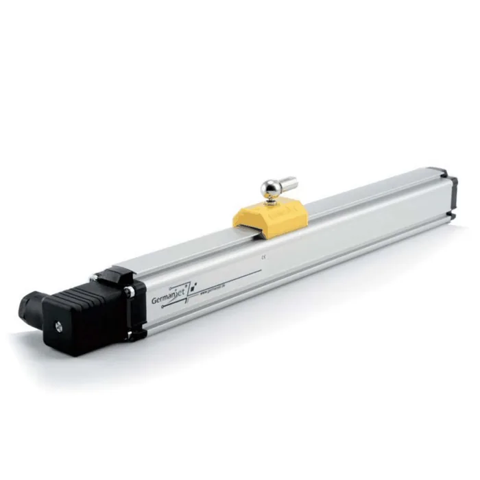
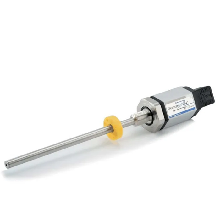

Whatever the question above, it comes back to the same device.magnetostrictive displacement sensorThe product range lists every series by stroke, mounting style and output interface, which is the quickest way into a selection.
← Back to News