
How Often Should a Magnetostrictive Displacement Sensor Be Calibrated?
An annual calibration ticket gets signed, the sensor comes back, and the machine still reads wrong. Most of the time the calibration was done and the wrong thing was done. Zero setting, accuracy calibration and cross-checking are three jobs. Rolled into one, the money gets spent and the problem stays.
1. "Calibration" Covers Three Different Jobs
The purposes differ, so the intervals differ.
- Zero setting. Aligns one known mechanical position to an agreed number. It shifts the whole curve; it does not change its shape. Afterwards, with the cylinder at the mechanical zero, the reading should be zero or whatever value was agreed.
- Accuracy calibration. Brings the curve itself back inside specification, which involves gain and linearity. It needs reference values at several positions from a standard, which a plant floor rarely has. This is the part that goes out or back to the factory.
- Cross-checking. Adjusts nothing. Uses two sensors, or a sensor and a mechanical gauge, to find out whether there is an offset and how big. It decides whether repair is needed; it does not perform the repair.
The practical value of separating them: most sites are short of the first, and send the sensor out for the second. The gap between the two is the sentence "we had it calibrated and it still drifts".
2. When Zero Must Be Redone, Regardless of Interval
Magnetostrictive measurement is absolute, so position survives a power cut. What survives is the electronic part. If the mechanical datum moved, absolute position will faithfully report the wrong place.
- The whole sensor was replaced. The new unit was calibrated against its own probe scale. Fitted into the same cylinder, its zero need not land on the same number.
- The magnet ring was removed and refitted. The ring's position is the measured position. One refit can shift it by a fraction of a millimetre, and the reading moves with it.
- The cylinder was reworked or resealed. After the gland or flange is reassembled, the axial datum of the probe changes.
- The mounting bracket was disturbed. Most visible on external types: move the bracket, move the zero.
- An offset was edited in the PLC. This is the one that fights itself. There is a zero in the sensor and an offset in the program. Once both have been touched, nobody can say which one is authoritative.
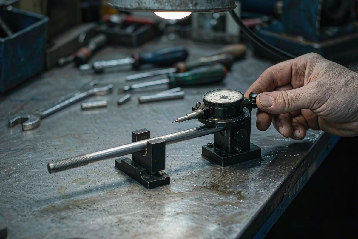
The check is plain: drive the cylinder to its mechanical zero, bottom it out if it can be bottomed out, and look at the reading. If it is not zero, redo the zero. No interval required.
3. Accuracy Follows Drift, Not the Calendar
A fixed inspection interval is the easiest thing to administer and it answers the wrong question: what is this machine allowed to be wrong by, and how far has it actually gone.
The usable criterion is the error budget. Of the total error the loop can tolerate, the measurement chain gets a share. The sensor's own tolerance consumes part of that share, and the remainder is the room left for drift. While drift stays inside that room, leave it alone. When it exceeds it, adjust or replace.
By duty, a rough ordering is possible; a specific interval is not:
- High temperature, dirty oil, heavy vibration. Start from cross-check results. Degradation in these conditions does not run to a schedule, and a calendar-driven inspection plan falls behind.
- Stable machines. Stretch the cross-check interval and watch the position curve of the same motion. The trend shows up earlier than an inspection report.
- Points inside a closed loop, or in a safety interlock. The tolerance is smaller to begin with. Cross-check more often; do not share one schedule with display-only points.
4. Two Jobs a Site Can Do Itself
Zero reset
Drive the machine to the agreed datum, then write the current reading to zero through the programmer or over the bus. Verify immediately: exit the menu, re-enter, and confirm the value held. Values that are not written to EEPROM revert on power-down; that subject is covered in our programmer setup article.
Three-point, out-and-back check
Take 0%, 50% and 100% of stroke. At each point travel out and back, and record the readings. Then look at two things:
- Out-and-back difference. Same mechanical position, different reading coming and going. The size of that difference is the size of the repeatability problem.
- Proportionality. If the deviation at mid-stroke is not proportional to the deviation at the ends, linearity has changed. That is more than a zero offset.
These are the same motions used at incoming acceptance. There the purpose is pass or fail; here it is drift.
5. Signs That Pre-empt the Interval
- The reading creeps in one direction while the machine stands still, worst at the end of stroke. That is zero drift, not noise.
- Out-and-back readings disagree and the gap grows over time. Check mechanical play and ring fixation before blaming the sensor.
- Mid-stroke is off while the ends agree, or the reverse. Linearity has moved.
- The reading shifts systematically once temperature rises, cold machine and hot machine disagreeing. Separate thermal expansion from sensor drift before condemning the sensor.
Only the third of these has to go out. The first two are frequently mechanical.
6. After the Sensor Comes Back
- Redo zero. Do not carry over the value from before the service.
- Confirm direction. On reversed or inverted mounting, a mistaken travel direction produces a reading that moves but is not right.
- Confirm the range coefficient. If the program converts raw counts against a fixed full-scale, a different sensor means a different full-scale count.
- Record the old value, the new value and the reason together in the machine file. Recording only the new value sends the next person back to the start.
7. One Line to Close
Zero is a site job. Accuracy is an out-of-house job. Put them on separate tickets, and the problem separates with them.
Frequently Asked Questions
Q: Does a magnetostrictive displacement sensor need annual calibration?
There is no universal interval. Zero setting depends on whether the mechanical datum moved; if it did, redo it at once. Accuracy depends on whether measured drift has exceeded the room allowed by that machine. Treating both as one annual job produces calibrations that leave the fault in place.
Q: What is the difference between zero setting and accuracy calibration?
Zero setting applies a pure shift, aligning one known mechanical position to an agreed number. Accuracy calibration adjusts gain and linearity and needs reference values at several positions. The first takes under an hour on site; the second usually goes out or back to the factory.
Q: How do you check without a standard gauge on site?
The mechanical datum is the gauge. Bottom the cylinder against a hard stop or use a limit block, then run a three-point out-and-back check at both ends and mid-stroke. Without an external reference you cannot calibrate accuracy, but you can reset zero and judge drift.
Q: After fitting a new sensor, must the PLC parameters change?
It depends where the conversion happens. If the program scales raw counts against a fixed full-scale value, a different full-scale count or range means recalculating the coefficient. If conversion happens inside the sensor and the PLC reads engineering units, only zero needs redoing, plus one check that the range matches.
Related Products
Related Applications

Series 12 General-Purpose Magnetostrictive Displacement Sensor Application Cases
View Details
Series 16 Hydraulic Rod Magnetostrictive Displacement Sensor Application Cases
View Details
Series 19H Cylinder-Integrated Process Displacement Sensor Application Cases
View DetailsWhatever the question above, it comes back to the same device.magnetostrictive displacement sensorThe product range lists every series by stroke, mounting style and output interface, which is the quickest way into a selection.
← Back to News