
A Start-Stop Displacement Sensor: Pulse Timing Handed to the Controller
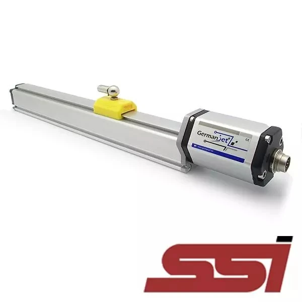
A Start-Stop displacement sensor moves the time measurement into the controller, keeping wiring simple but demanding fast timing. It is the most "primitive" and most direct output of a magnetostrictive sensor: the controller issues a Start pulse to trigger a measurement; the sensor issues a Stop pulse when the echo arrives; the time difference between the two pulses, multiplied by the propagation speed of the torsional wave in the waveguide, is the distance from the magnet to the fixed end. It moves the time-measurement step from the sensor electronics head to the controller, so the interface is extremely simple, but it demands high-speed timing capability from the controller, and acoustic-velocity temperature drift must be compensated on the controller side. This article sets out the application bounds; for the measurement principle see Magnetostriction and the Wiedemann Effect Explained.

How it works: handing the timing to the controller
The physical chain of magnetostrictive measurement is: the electronics head sends a current pulse into the waveguide → the current field and the magnet field superimpose, producing a torsional stress wave at the magnet (the Wiedemann effect) → the torsional wave travels along the waveguide back to the fixed end → the sensing coil picks up the echo. The time from issuing the current pulse to detecting the echo is proportional to magnet position. For the division of labour inside the electronics head see What's Inside the Electronics Head: Pulse Circuit, Echo Detection and Output Stage.
On interfaces such as SSI and CANopen, this time difference is measured by a high-precision timing circuit inside the electronics head and converted to a position value before output. The Start-Stop interface sends the two time marks out as pulses: the Start pulse corresponds to the instant the interrogation is issued, the Stop pulse to the instant the echo is detected. The controller measures the interval with a high-speed counter and converts position itself.
The core consequence is that half the responsibility for system accuracy sits on the controller. The resolution and stability of the controller's timing clock directly determine the final position-resolving capability. This is a fundamental difference from other interfaces, where "accuracy is determined by the sensor".
Applications and hard premises
Start-Stop still has practical value in two situations. First, the controller itself has a dedicated magnetostrictive interface module (some hydraulic-dedicated controllers and older-generation injection molding control systems fall in this class); the module already integrates timing and conversion, so wiring is simplest and cost is lowest. Second, on a retrofit the original system is already Start-Stop wired, and keeping the interface when replacing the sensor avoids changing the control program. The Series 12 general-purpose offers analog voltage, current and Start-Stop digital signal as three interface choices, a typical configuration for this scenario.
There are three hard premises:
- The controller must have a high-speed timing input. The ordinary digital-input scan cycle of a general-purpose PLC is far too slow to resolve the pulse interval; a dedicated high-speed counter module or dedicated interface module is required.
- Differential transmission and shielding must be done properly. The arrival instant of the pulse edge is the measurement result itself; an edge distorted by interference equals a wrong position reading. RS-422 differential transmission is usual, with the shield earthed to specification.
- Acoustic-velocity temperature drift must be considered. The propagation speed of the torsional wave in the waveguide varies with temperature. On applications with large temperature change, if the controller side does not compensate, the result is an overall zero and span drift. For the practical magnitude of temperature effects and the warm-up / thermal-equilibrium mechanism see Do Sensors Need Warm-Up? Self-Heating, Thermal Equilibrium and the Real Magnitude of Temperature Effects.
Start-Stop compared with other interfaces
| Dimension | Start-Stop | SSI | Analog (4-20 mA / 0-10 V) | Fieldbus (CANopen and similar) |
|---|---|---|---|---|
| Where position is converted | Controller | Sensor | Sensor | Sensor |
| Demand on the controller | High-speed timing module needed | SSI module needed | Ordinary analog input | Corresponding fieldbus master needed |
| Key to noise immunity | Integrity of the pulse edge | Quality of clock/data differentials | Loop voltage drop and common-mode interference | Differential bus and termination matching |
| Multi-device sharing of the wire | No | No (point-to-point) | No | Yes |
| Diagnostics | Essentially none | Weak | None (wire-break detection can be used) | Strong |
| Where temperature-drift compensation sits | Must be handled on the controller side | Inside the sensor | Inside the sensor | Inside the sensor |
| Typical use | Dedicated controllers, legacy retrofits | Single-axis high-speed digital reading | General-purpose, low retrofit cost | Multi-axis; diagnostics and configuration needed |
Should a new project still choose it?
The conclusion is: unless the controller natively supports it, Start-Stop is generally not recommended for new projects. The reason is that it splits the responsibility for accuracy and temperature-drift compensation onto the controller side, adding software complexity and commissioning uncertainty, while diagnostic capability is almost nil — when something goes wrong there is neither device status to see nor parameters to read remotely. At comparable cost, SSI gives better determinism, analog gives a lower access threshold, and fieldbus types give diagnostics and multi-axis capability. Unless the controller natively supports it, Start-Stop is generally not recommended, diagnostics being nearly nil; keep it only on a legacy retrofit already wired for it.
On a legacy retrofit where it must be retained, confirm three things: the controller interface-module type and level standard, whether the conversion factor is configurable, and whether the temperature duty requires compensation. For the cylinder-integrated mounting form see Series 17 Hydraulic Cylinder Integrated Explained; the corresponding product page is Series 17. For the full decision path across interface families see Analog vs. Digital Across the Whole Range; for the overall output-selection framework see Selecting a Magnetostrictive Displacement Sensor: 4-20 mA Analog or CANopen Fieldbus?.
Frequently Asked Questions
Q: How does a Start-Stop interface measure position?
The controller issues a Start pulse to trigger a measurement; the electronics head interrogates the waveguide, and when the torsional wave travelling from the magnet back to the fixed end is detected the sensor outputs a Stop pulse. The time difference between the two pulses, multiplied by the propagation speed of the torsional wave in the waveguide, is the distance from the magnet to the fixed end.
Q: Can an ordinary PLC take Start-Stop directly?
No. The scan cycle of ordinary digital inputs is far too slow to resolve the pulse interval. A dedicated high-speed counter module or a magnetostrictive interface module built into the controller is required; otherwise the measurement cannot be accurate.
Q: Why must Start-Stop compensate temperature drift on the controller side?
The propagation speed of the torsional wave in the waveguide varies with temperature. Other interfaces complete conversion and compensation inside the electronics head; Start-Stop moves conversion to the controller, so on applications with large temperature change, if the controller does not compensate, zero and span will drift as a whole.
Q: Should a new project still choose Start-Stop?
Generally no, unless the controller natively supports the interface. It splits the responsibility for accuracy and temperature-drift compensation onto the controller, adding software complexity, and diagnostic capability is almost nil. At comparable cost SSI is more deterministic, analog has a lower threshold, and fieldbus types bring diagnostics and multi-axis capability.
Q: What should I watch when retaining Start-Stop on legacy equipment?
Confirm three things: whether the controller interface-module type and level standard match the new sensor, whether pulse polarity is consistent, and whether the conversion factor is configurable; also assess whether the site temperature duty requires compensation.
Related Products



Related Applications

Multi-Industry Application Cases for Magnetostrictive Displacement Sensors
View Details
Series 12 General-Purpose Magnetostrictive Displacement Sensor Application Cases
View Details
Series 17 Hydraulic Cylinder Integrated Magnetostrictive Displacement Sensor Application Cases
View Details