
Vulcanising Press Heat: Displacement Sensor Stability Over Accuracy
For a magnetostrictive displacement sensor on a rubber vulcanising press, temperature tolerance and long-term drift come first. Unlike other pressing equipment, it works for long periods in high-temperature radiation and steam, and the process cycle is counted in minutes rather than seconds. Clamp position determines how fully the cavity closes and how much compound flashes; displacement, temperature and pressure together form the vulcanising process curve. The first selection constraint is therefore temperature endurance and long-term drift, and only then resolution — a micrometre-level resolution is not a hard need here; stability without drift is.
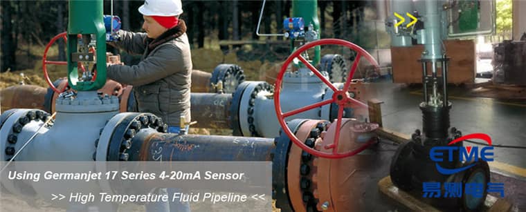
The role of position feedback in the vulcanising process
Clamp displacement has three functions in the vulcanising process: first, cavity-close confirmation, judging whether the upper and lower moulds are fully seated, to prevent flash and under-pressure; second, clamp-speed staging, decelerating near close to protect the mould and inserts; third, position monitoring during vulcanising — a slow position change in the hold stage indicates internal leakage or abnormal compound flow. The third is often overlooked, yet it is an effective indicator of equipment degradation: on the same mould and the same compound, a month-by-month change in the in-position clamp reading often appears before a quality problem.
High-temperature radiation and thermal drift: two accounts that must be calculated first
Platen temperature is high, and parts near the platens see radiant heat for long periods. Two accounts must be distinguished: the first is the sensor’s own operating-temperature limit, which must be checked as operating temperature, not storage temperature (the distinction is in Operating Temperature vs. Storage Temperature); the electronics head in particular cannot tolerate continuous high temperature. The second is measurement drift caused by temperature: waveguide sonic velocity changes with temperature and shifts zero and span; mechanism and compensation are in Do Sensors Need Warm-Up? Self-Heating, Thermal Equilibrium and the Real Magnitude of Temperature Effects. Routine engineering practice is: keep the electronics head away from the heat source, add a heat shield, and if necessary use a split type (electronics head mounted separately from the rod) — see Series 19D split type.
Comparison of mounting forms
| Scheme | Heat endurance | Retrofit difficulty | Measuring-chain length | Suited to |
|---|---|---|---|---|
| In-cylinder in the clamp cylinder | Good (rod in the cylinder, affected by oil temperature) | Piston rod must be deep-bored | Short | New-machine design, major overhaul |
| Integral external | Moderate (electronics head exposed to radiant heat) | Low | Medium | Quick add-on to in-service machines |
| Split external | Good (electronics head can be kept from the heat source) | Medium | Medium | Machines with high temperature near the platens |
| Limit switch (for comparison) | Good | Low | — | Two states only; no curve or trend |
Similarities and differences with die-casting and pressing equipment
A vulcanising press and a die-casting machine are both clamp-type equipment, but die casting emphasises high update rate and instantaneous shock on the shot section (see Real-Time Position Feedback for Die Casting Machine Clamping), whereas a vulcanising press emphasises stability under long high temperature and smoothness of slow clamping. Compared with a servo hydraulic press, a vulcanising press needs one or two orders of magnitude less position resolution (compare High-Accuracy Pressing Position on Servo Hydraulic Presses). There is no need to chase a high-accuracy step at selection; a 10–20 μm step with repeatability of the order of ±0.002 mm is enough to support the process closed loop. In-cylinder schemes include Series 16 cylinder-integrated; the general hydraulic-circuit selection framework is in Why Choose Magnetostrictive Sensing for Hydraulic Cylinder Position Control.
Signal interface and process-data retention
Vulcanising presses often run several platens and moulds at once, so the controller must acquire several displacement channels together. Analog schemes involve a lot of wiring; a fieldbus can cut connections significantly and carry diagnostics. Once process data (the four curves of time–temperature–pressure–displacement) are retained, they can be used to analyse consistency of the same mould across shifts. Fieldbus wiring and termination points are in How to Connect Magnetostrictive Displacement Sensors to a Fieldbus. If a reading drifts slowly on site, first rule out thermal drift and steam in the connector, then follow Troubleshooting Magnetostrictive Displacement Sensors.
Practical tips for engineers
- Series 19F front dead zone: 50 mm for stroke <8000 mm, 130 mm for stroke >8000 mm. Always deduct this when calculating the usable measuring stroke.
- Overall sensor length tolerance: +8 mm for stroke <8000 mm, +15/−5 mm for stroke >8000 mm; this tolerance does not affect the measuring stroke.
- Series 19F minimum stroke is 250 mm; for shorter strokes choose another series.
Frequently Asked Questions
Q: Is temperature alone enough for vulcanising quality?
No. Clamping pressure is determined by platen closed position; insufficient position under-presses, excessive position damages the mould. Displacement must be coordinated with temperature control.
Q: How is a hot platen protected against?
Keep the electronics head away from the platen; if necessary use a split type and move the electronics head out of the hot zone. Check the dual constraint of operating temperature and oil temperature.
Q: How is parallelism of a multi-platen vulcanising press measured?
Fit sensors of the same type on each platen and monitor the inter-platen difference curve; drift at a single point often points to internal leakage of that layer’s cylinder.
Related Products



Related Applications

Multi-Industry Application Cases for Magnetostrictive Displacement Sensors
View Details
Series 16 Hydraulic Rod Magnetostrictive Displacement Sensor Application Cases
View Details
Series 17 Hydraulic Cylinder Integrated Magnetostrictive Displacement Sensor Application Cases
View Details