
Series 12 General-Purpose Magnetostrictive Displacement Sensor Explained: Structure, Specifications and Applications
Series 12 is the general-purpose line in Germanjet's magnetostrictive displacement sensors, positioned as "the default choice when there is no special duty constraint": construction is the classic three-part arrangement of electronics head + rigid rod + moving position magnet; measurement is non-contact absolute-position output. Resolution is listed by output: analogue voltage type (120) lists resolution as infinite (depends on the controller A/D and supply ripple), repeatability < ±0.005% FS, non-linearity < ±0.01% FS (min. ±90 μm), update time 0.2 ms; digital analogue type (121) is the 16-bit D/A, 0.0015% (min. 1 μm). It is not specially reinforced for high-pressure in-cylinder duty, hazardous areas or high-vibration mobile machinery, so it offers the best value on general machine tools, test stands, assembly lines and light-duty hydraulic equipment.
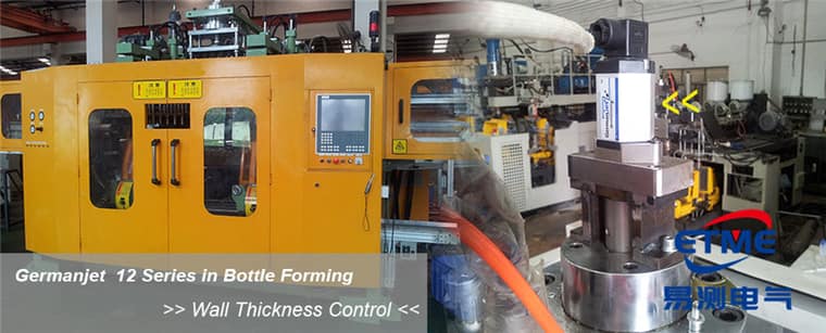
Product positioning of Series 12
In the product matrix, series differ mainly on two dimensions — "mounting method" and "environmental reinforcement" — not on measuring principle. Series 12 takes general-purpose values on both: mounting is external, environmental protection is a conventional IP rating (IP65/67 available by model), and it does not take internal cylinder pressure. In other words, any displacement-measurement task that does not need to enter a cylinder, is not in an explosive-gas atmosphere, and does not see continuous whole-machine vibration can be covered by Series 12.
Duty that must enter a cylinder and take pressure should move to the Series 16 in-cylinder hydraulic type or the Series 17 integrated type; high-vibration mobile hydraulic equipment should move to Series 13; hazardous areas must use the Series 17EX intrinsically safe type. These boundaries are fully compared in product-matrix selection overview.
Construction and the role of each part
The physical construction of Series 12 can be split into three parts; understanding each role helps site troubleshooting:
- Electronics head: contains the pulse-generation circuit, echo-detection circuit and output module; it launches the current pulse, captures the torsional-wave echo, converts position and outputs on the selected interface. Internal roles are covered in what is inside the electronics head.
- Measuring rod (waveguide tube): a stainless-steel tube enclosing an iron–nickel magnetostrictive-alloy waveguide, the physical carrier of position information. The rod itself does not take part in the motion; it is mounted stationary throughout.
- Moving position magnet: a permanent magnet that rides on the outside of the rod and moves with the measured mechanism; its spatial position is the measured position. A non-contact clearance is kept between magnet and rod, so there is theoretically no wear.
Because position is determined directly by the magnet's physical location, Series 12, like the whole range, outputs absolute position and does not need to home after a power cycle; the principle is in absolute vs. incremental position.
Core specifications and how to read them
| Specification | Series 12 value | How to read it |
|---|---|---|
| Measuring principle | Magnetostrictive (Wiedemann effect) | Non-contact; no mechanical wear between rod and magnet |
| Output nature | Absolute position | Position not lost on power-down; no homing or reference-point switch |
| Resolution | 120: infinite (controller A/D); 121: 16-bit D/A 0.0015% (min. 1 μm) | Do not write 121’s 16-bit figure onto 120 |
| Repeatability | 120: < ±0.005% FS; 121: < ±0.001% FS (min. ±2.5 μm) | Main criterion of closed-loop positioning stability |
| Non-linearity | 120: < ±0.01% FS (min. ±90 μm); 121: < ±0.01% FS (min. ±40 μm) | Relative to full scale; convert to absolute error together with measuring range |
| Mounting | External; rod fixed, magnet follows | Does not take internal cylinder pressure |
| Output interface | Analog (0-10 V / 4-20 mA) and Start/Stop digital, by model | Interface decides downstream wiring |
The differences among the three accuracy figures and common misreadings are already unpacked in the three accuracy terms and are not repeated here. When specifying, note especially that non-linearity is %FS: the same 0.02%FS is ±0.02 mm on a 100 mm range and ±0.4 mm on a 2000 mm range — a mathematical result of the range base, not a drop in product performance.
Differences from dedicated series
| Comparison | Series 12 general-purpose | Series 13 mobile hydraulic | Series 16 / 17 in-cylinder |
|---|---|---|---|
| Mounting location | Outside the machine, independent bracket | Outside mobile machinery, vibration-reinforced | Into the cylinder cavity |
| Pressure rating | Not pressurised | Not pressurised | 350 / 530 bar (Series 16) |
| Protection rating | Conventional IP rating | Up to IP69K | Inside the cylinder, sealed by the cylinder body |
| Vibration / shock | Conventional | 25 g vibration / 100 g shock | Protected by the cylinder body |
| Typical duty | Machine tools, test stands, assembly lines | Construction machinery, agricultural machinery, marine | Injection molding, die-casting, hydraulic presses |
| Machining changes | No change to the machine body | No change to the machine body | Piston-rod bore required (≥12.7 mm, Ø10 rod) |
Typical applications
Series 12 is most often chosen in the following cases:
- Linear-axis position feedback on machine tools and special-purpose machines: medium stroke, clean environment, accuracy requirement dominated by repeatability;
- Test stands and inspection equipment: a continuous displacement curve is needed rather than only in-position signals; analog output into a data-acquisition card is enough;
- Assembly-line positioning and lifting mechanisms: replacing wearing potentiometric resistive scales; non-contact wear brings longer life;
- Adding displacement sensing to older machines: no cylinder work and no production stop for the retrofit; external mounting is enough — see the bracket-adaptation method in Series 18 externally mounted type explained.
Conversely, if the site has oily high-pressure wash-down, explosive gas, continuous shock load or an in-cylinder mounting need, choose a dedicated series directly rather than adding a cover to Series 12 as a compromise — a cover brings heat-dissipation and standing-water problems. What protection ratings actually mean is in what IP65/67/68/69K really mean.
Installation and wiring points
The great majority of Series 12 site problems come from installation, not from the product itself. Three high-frequency points:
First, concentricity of magnet and rod. The magnet must not touch the rod, nor run too far off-centre. Eccentricity makes the magnetic working zone asymmetric and appears as reading drift on local segments. Installation tolerances and common errors are in position-magnet selection and mounting.
Second, dead zones at both ends of the measuring range. The root and tip of the rod each have an inactive zone; mechanical stroke must not push the magnet into a dead zone, or the output will stick at an end value or jump. When specifying, leave margin on the actual stroke; details are in dead zones at both ends of the effective range.
Third, screening and earthing. Analog-output models are more sensitive to interference; single-end earthing of the screen is the general practice; near inverters and servo drives, run separately from power cables. Troubleshooting is in common fault finding.
Choose the output interface from the downstream system: if the PLC has only analog input cards, use the matching configuration of the Series 191 analog; if multi-axis digital communications and diagnostic information are needed, use the decision framework in analog or fieldbus.
Frequently Asked Questions
Q: What applications suit the Series 12 general-purpose magnetostrictive displacement sensor?
Applications that do not need to enter a cylinder under pressure, are not in an explosive-gas atmosphere, and do not see continuous whole-machine vibration — for example machine-tool linear axes, test stands, and assembly-line positioning and lifting mechanisms. It uses external mounting and outputs absolute position. 120 lists infinite resolution (controller A/D); 121 is the 16-bit D/A.
Q: How does Series 12 differ from Series 13 and Series 16?
The difference is mounting method and environmental reinforcement, not measuring principle. Series 12 is a general-purpose external type with a conventional IP rating; Series 13 is reinforced for mobile hydraulic duty, up to IP69K, 25 g vibration and 100 g shock; Series 16 is an in-cylinder hydraulic type requiring piston-rod bore ≥12.7 mm (Ø10 rod) and taking 350 bar working / 530 bar peak.
Q: How should Series 12 resolution steps be chosen?
Look at the order code first. 120 analogue voltage lists infinite resolution, which actually depends on the controller A/D and supply ripple — not 1–100 μm steps. 121 digital analogue is the 16-bit D/A, 0.0015% (min. 1 μm). Resolution only characterises the smallest distinguishable position increment, not accuracy. Positioning applications should still take repeatability and non-linearity as the main criteria.
Q: Does Series 12 need to home after power-down?
No. A magnetostrictive displacement sensor outputs absolute position; position is determined by the physical location of the magnet on the waveguide and does not rely on electronic counting. After a power cycle the correct position is read at once, and no reference-point switch is required.
Related Products




Related Applications

Multi-Industry Application Cases for Magnetostrictive Displacement Sensors
View Details
Series 12 General-Purpose Magnetostrictive Displacement Sensor Application Cases
View Details
Series 17 Hydraulic Cylinder Integrated Magnetostrictive Displacement Sensor Application Cases
View Details