
TBM Thrust Cylinders: Grouped Displacement Sensor Synchronisation
A magnetostrictive displacement sensor on a tunnel boring machine (TBM) reads the thrust-cylinder strokes that set shield attitude. The advance attitude is determined directly by the grouped stroke difference of the thrust cylinders: different extensions of the upper, lower, left and right cylinder groups produce pitch and yaw of the shield. Thrust-cylinder position feedback is therefore not an auxiliary monitor but the input to steering control. Tunnel duty — high humidity, slurry, dust, confined space, long cable runs, and no ability to stop for maintenance at will — means an in-cylinder absolute-position scheme must be chosen here, with design margin left for long-distance signal transmission and redundancy.
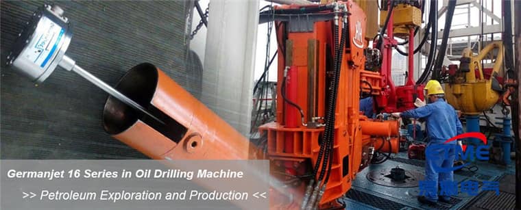
Three tasks of thrust-cylinder position feedback
First, stroke and advance-quantity statistics: the advance stroke of a single ring determines when to stop and assemble segments, and the stroke reading directly triggers the step-change sequence. Second, attitude correction: grouped stroke difference is converted geometrically into shield attitude error and cross-checked against guidance-system data. Third, synchronisation and protection: when several cylinders move together, stroke consistency must be monitored to prevent individual cylinders stalling under pressure or overtravelling. All three require that position remain valid after power loss, stop and re-power; absolute-position output is therefore a premise (the principle is in Absolute vs. Incremental Position).
Selection constraints of the tunnel environment
Tunnels are continuously humid with condensation; slurry and dust are present near the face, and wash-down may hit the unit with a water lance. Protection class IP67 and above is recommended, IP69K in wash-down zones (class differences in IP65/67/68/69K Is Not a Numbers Game). The thrust system is a high-pressure hydraulic circuit; the in-cylinder pressure rating must cover peak pressure (by series: Series 16/16R is 350 bar working / 530 bar peak, Series 17/17EX is 350/600 bar, Series 19 in-cylinder is 300/600 bar), and the piston-rod deep bore is generally ≥12.7 mm minimum. An exposed-rod scheme cannot be relied on for life in this environment unless a dependable mechanical guard is fitted. In-cylinder products include Series 16 cylinder-integrated; integrated schemes include Series 17 hydraulic-cylinder integrated. General hydraulic closed-loop points are in Why Choose Magnetostrictive Sensing for Hydraulic Cylinder Position Control.
Interface comparison: how to choose for long-distance transmission
| Interface | Long-distance behaviour | Multi-node capability | Diagnostics | Suited to |
|---|---|---|---|---|
| 4-20 mA | Good (current loop resists voltage drop) | One cable per channel; heavy wiring | None | Few cylinders; analog cards already present |
| SSI | Medium (limited by clock frequency and cable length) | Point-to-point | Limited | High-speed position loop |
| CANopen | Good (distance can be extended by dropping speed) | Strong; many nodes on one line | Rich | Grouped multi-cylinder, centralised acquisition |
| Profibus DP | Good | Strong | Rich (GSD diagnostics) | Large-PLC main-control lines |
Multi-cylinder wiring: reducing the cable count
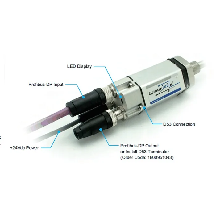
A TBM has many thrust cylinders; one analog channel per cylinder puts heavy pressure on control-cabinet terminals and cable trays, and fault location is slow. A more common engineering practice is to place remote I/O or bus nodes nearby by zone and bring the zone’s cylinder positions back to the main controller on one bus. When using a fieldbus, watch the mutual constraint of baud rate and bus length, correct terminating-resistor configuration, and node-address planning — practice in How to Connect Magnetostrictive Displacement Sensors to a Fieldbus; Profibus models include Series 195 Profibus. If occasional data loss occurs, first check terminating resistors, address conflicts and water in connectors, in the order of Troubleshooting Magnetostrictive Displacement Sensors.
Differences from other heavy hydraulic scenes
TBMs and construction machinery both belong to heavy mobile hydraulics, but the difference is marked: construction machinery emphasises shock resistance and vehicle CAN integration (see Construction Machinery Cylinders: Position Solutions for Excavators and Loaders), whereas a TBM emphasises multi-cylinder consistency, long-distance transmission and uninterrupted running. Critical groups should be assessed for redundancy or dual-channel comparison, so that a single-point failure does not interrupt the drive; redundancy thinking is in What Is Redundant Output? The Story Behind Dual-Channel Safety Design.
Practical tips for engineers
- For in-cylinder mounting, piston-rod bore lower limit is ≥12.7 mm (Ø10 rod). Series 17 also has a Ø13 mm through-hole + M18×1.5 on the cylinder cap; Series 16 uses Ø18G7. Do not mix pressure ratings: Series 16/16R is 350 bar working / 530 bar peak, Series 17/17EX is 350/600 bar, Series 19 in-cylinder is 300/600 bar.
- The sensor rod should be protected against wear inside the cylinder.
- Series 19 in-cylinder types are rated 300 bar with a 600 bar peak; use these figures for selection and pressure testing.
Frequently Asked Questions
Q: What happens if TBM cylinders are not synchronised?
Shield attitude drifts and must be corrected. Synchronous sampling of several sensors of the same type to monitor inter-cylinder difference is the basis of attitude control.
Q: Is position lost if power is cut during segment assembly?
No. Each cylinder’s absolute position is read independently and is available immediately after restoration, with no cylinder-by-cylinder homing, so disorder is avoided.
Q: How is a slurry environment protected against?
Choose IP67 or above, reinforce connector seals, and run cables in conduit; if necessary use Series 13 IP69K against wash-down.
Related Products



Related Applications

Multi-Industry Application Cases for Magnetostrictive Displacement Sensors
View Details
Series 17 Hydraulic Cylinder Integrated Magnetostrictive Displacement Sensor Application Cases
View Details
Series 19P External Rod Process Displacement Sensor Application Cases
View Details