
Woodworking Press and Feed: Dust-Protected Displacement Sensor
Dust is the most underestimated factor in a magnetostrictive displacement sensor on woodworking machinery. Measurement concentrates on two lines: the press line (platen stroke on hot presses, cold presses and laminators, which determines panel thickness and pressing quality) and the processing line (feed and positioning on CNC panel saws, multi-spindle drills and edgebanders, which determine finished dimensions). Both lines share an environment of airborne wood dust, glue splash and, at some stations, hot-press heat. Dust is the factor most often underestimated here — it builds up on guideways, brackets and the magnet face, gradually changing the mechanical fit rather than causing an immediate electrical fault.
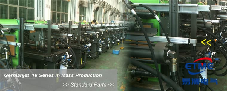
Press line: platen stroke and thickness consistency
The finished thickness of a hot-pressed panel is determined by the platen closing position (except on machines that use thickness gauges as mechanical stops). Displacement feedback serves three purposes: closing-position control, multi-point platen parallelism monitoring, and hold-position monitoring during the press cycle. Multi-point monitoring is the key point — if the positions at different points on a large-format press are inconsistent, panel thickness will vary by zone. Multi-channel sensors should be the same model and the same measuring range, On wide presses, several uniform sensors monitor parallelism better than any single unit's rating, with attention paid to channel-to-channel consistency rather than the figures of a single unit; the rationale is given in resolution, repeatability and non-linearity. Hot-press stations also require a check of the ambient temperature; keep the electronics head away from the hot platen and, where necessary, specify a remote-electronics construction.
Processing line: feed and panel-cut positioning
The pusher on a CNC panel saw, the transverse positioning of a multi-spindle drill and the fence adjustment of an edgebander are all, in essence, linear positioning. These mechanisms are typically driven by a servo ballscrew or a rack-and-pinion, with native feedback from the motor encoder. Fitting a magnetostrictive sensor that measures the actuator-end position directly eliminates backlash and transmission error and provides absolute position — after a power loss the machine can continue without homing (see absolute vs. incremental position). For positioning applications a 5-20 μm resolution grade is recommended, and the refresh rate should be checked against the control cycle (see matching response time to the control cycle).
Typical measuring-point layout on woodworking machinery
| Measuring point | Control objective | Recommended form | Resolution grade | Environmental focus |
|---|---|---|---|---|
| Hot-press platen stroke | Panel thickness and pressing consistency | In-cylinder or remote-electronics profile | 10-20 μm | Radiant heat, steam |
| Cold-press / laminator platen | Closing position | In-cylinder | 20-50 μm | Glue splash |
| Panel-saw pusher | Cut size | Profile type | 5-10 μm | Wood dust |
| Edgebander / multi-spindle drill positioning | Hole location and fence | Profile type | 5-20 μm | Dust, vibration |
Installation points in a dusty environment
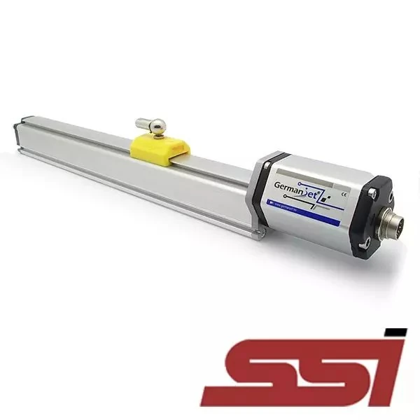
Wood dust is copious, dry, prone to build-up and combustible. Because a magnetostrictive displacement sensor measures without contact, dust only coats the magnet face rather than wearing a wiper. It still affects measurement in three ways: first, build-up between the magnet and the rod changes the gap and, over time, can cause unstable readings; second, a coating on the rod surface impairs heat dissipation; third, dust can enter connectors. Countermeasures: mount the rod below or to the side of the mechanism rather than directly above it (to reduce direct fall-out), fit a simple dust cover, and specify connectors to IP67 or better with the cable routed downwards (for the meaning of each rating see IP protection ratings). For profile-type products see Series 18 profile type; for wet areas or stations that require washdown, specify Series 13 mobile hydraulic. Installation practice is covered in installing and commissioning in practice.
Interfaces and line integration
Woodworking CNC equipment is typically built around a servo system. Position feedback may be SSI (deterministic timing, suited to the position loop) or a fieldbus type (convenient for centralised multi-axis management); for SSI models see Series 192 SSI digital interface. The selection framework for hydraulic circuits on the press line is given in why hydraulic cylinder position control uses magnetostrictive sensing. Similar pressing and tilting positioning requirements exist on glass machinery; see glass machinery: pressing and tilting positioning.
Practical tips for engineers
- Series 19F front dead zone: 50 mm for strokes <8000 mm, 130 mm for strokes >8000 mm; deduct this when calculating the usable stroke at the selection stage.
- Overall sensor length tolerance is +8 mm for strokes <8000 mm, and +15/-5 mm for strokes >8000 mm; this tolerance does not affect the measuring stroke.
- Series 19F has a minimum stroke of 250 mm; specify another series for shorter strokes.
Frequently Asked Questions
Q: What determines hot-press panel thickness?
The platen closing position. Multi-point sensors of the same model monitoring parallelism give a better picture of thickness consistency than the figures of a single unit.
Q: How should a wood-dust environment be protected?
Keep the rod out of the direct fall-out zone above the mechanism, fit a dust cover, and use IP67 or better connectors routed downwards; specify Series 18 for profile mounting and Series 13 for wet areas.
Q: Does CNC feed need homing?
Once an absolute-position sensor is fitted, homing is unnecessary: on power-up the pusher position is known immediately, reducing downtime.
Related Products


Related Applications

Multi-Industry Application Cases for Magnetostrictive Displacement Sensors
View Details
Series 18 Profile Magnetostrictive Displacement Sensor Application Cases
View Details
Series 19D Split-Type Process Displacement Sensor Application Cases
View Details