
Forging Ram Position: Blow-End Control Under Shock and Radiant Heat
Forging rams read absolute position with a magnetostrictive displacement sensor, where shock and heat are the two tests. Displacement feedback on forging equipment faces the harshest combination of duties in the industry: radiant heat from the billet, intense shock and vibration at the instant of the blow, scale spatter, and oil and cooling-water mist. Ram (or slide) stroke feedback is used for blow-position control, forging-height (blow end-point) control and energy allocation over multiple blows. Process-wise, forging dimensional consistency depends directly on the repeatability of the blow end-point, so the reliability of this feedback chain is equivalent to the product pass rate.
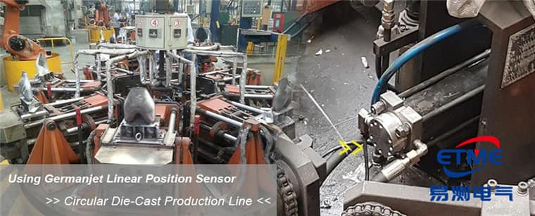
Three process tasks of forging displacement feedback
The first is blow end-point control: a hydraulic forging press stops on position; repeatability of the end-point determines forging-height tolerance. The second is stroke segmentation and speed control: rapid approach, forging and return are switched on position, reducing idle-stroke time. The third is process recording: the displacement–pressure curve of each blow is used for process traceability and die-life analysis. The practical meaning of repeatability (of the order of ±0.002 mm) here is “consistency under the same command”, not absolute accuracy; the conceptual distinction is in the three accuracy terms.
Reliability design in a high-shock environment
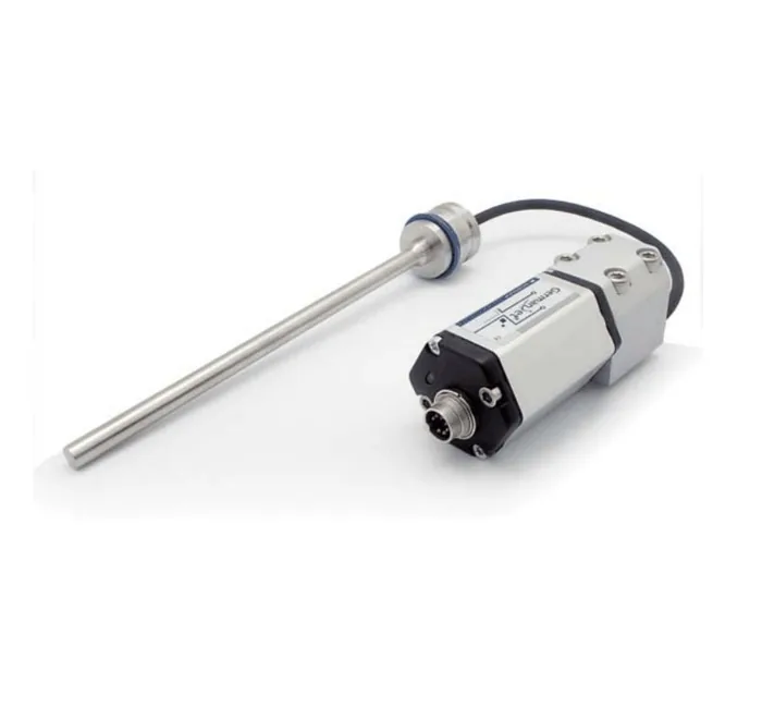
The shock acceleration produced by a hammer blow is extreme; any external bracket may crack or loosen under long-term shock. Forging equipment therefore prefers in-cylinder mounting: prefer in-cylinder mounting so the rod shares load with the cylinder and avoids independent-bracket fatigue; if a profile type is unavoidable, use a rigid base plus extra support points. The rod sits in a deep bore in the piston rod, shares the load with the cylinder as one piece, and has no independent-bracket fatigue problem; it also stays clear of scale and spatter. In-cylinder mounting requires a check of pressure rating (by series: Series 16/16R is 350 bar working / 530 bar peak, Series 17/17EX is 350/600 bar, Series 19 in-cylinder is 300/600 bar) and minimum bore (generally ≥12.7 mm). If a profile type is unavoidable, use a rigid base, add support points, and specify a model with high vibration and shock ratings (for example of the order of 25 g vibration / 100 g shock). Related products include Series 16 in-cylinder and Series 19H in-cylinder.
Installation schemes compared
| Scheme | Shock resistance | Radiant-heat resistance | Measuring chain | Maintainability |
|---|---|---|---|---|
| In-cylinder | Good | Fairly good (influenced by oil temperature) | Shortest | Requires a shutdown to strip the cylinder |
| Remote-electronics profile | Medium | Good (electronics head can be kept away from the heat source) | Medium | Good |
| Integral profile type | Poorer (bracket fatigue) | Ordinary | Medium | Good |
| Mechanical stops (comparison) | Good | Good | — | Two-state only, no process curve |
Handling high temperature and thermal drift
Ambient temperature in the forging area is significantly higher than in an ordinary shop, and it fluctuates with production rhythm. Selection must check the operating-temperature range (for the distinction see operating temperature vs. storage temperature). Speed-of-sound drift caused by temperature change produces zero and span offsets; the mechanism and compensation are in speed-of-sound temperature drift and compensation. Engineering practice: keep the electronics head away from the radiation source, add heat shields, and, where necessary, specify a remote-electronics construction (Series 19D remote-electronics); and determine the process zero by calibration after the machine is thermally soaked.
Electromagnetic environment and signal integrity
Induction furnaces, medium-frequency supplies and high-power drives form a strong electromagnetic environment. Coupled interference on signal cables can cause reading jumps at the instant of heating or of a blow. The countermeasures are similar to those on a mill line: separate trunking, screen earthed at one end, and avoid running parallel to high-current busbars; see EMC. The general selection framework for a hydraulic closed loop is given in why hydraulic cylinder position control uses magnetostrictive sensing. For a comparison with precision pressing equipment see high-accuracy pressing position on servo hydraulic presses.
Engineering application notes
- A 6600-tonne two-platen injection-molding machine used a Series 19, 7600 mm stroke, CAN bus scheme for full-stroke mould-closing position feedback.
- Mould-closing speed on a die-casting machine can reach 10 m/s; a digital-interface model with sufficiently fast response must be specified.
- Steel rolling-mill roll-gap control specifies Series 19 with SSI output; woodworking forming machines and packaging machines (IP67 environments) are often fitted with Series 17/18.
Frequently Asked Questions
Q: Why measure displacement on a forging-hammer ram?
Blow position and stroke determine forging form. Displacement feedback is used for stroke control and overload protection.
Q: Can it withstand high shock?
Series 13 is rated 100 g shock and 25 g vibration, designed for shock duty; the mounting must be stiffened against loosening.
Q: How is a hot forging protected against?
Keep the electronics head away from forging radiant heat and, where necessary, use a remote-electronics construction; check operating temperature.
Related Products



Related Applications

Multi-Industry Application Cases for Magnetostrictive Displacement Sensors
View Details
Series 16 Hydraulic Rod Magnetostrictive Displacement Sensor Application Cases
View Details
Series 19D Split-Type Process Displacement Sensor Application Cases
View Details