
Wind Pitch Cylinder: Absolute Displacement Sensor in the Hub
A magnetostrictive displacement sensor on a wind pitch cylinder gives the stroke from which blade angle is derived. Pitch angle on a hydraulic-pitch wind turbine is not measured directly; it is obtained from pitch-cylinder stroke through the mechanism conversion. This feedback chain sits on two logics at once: in normal running it is used for power control and load regulation; in abnormal duty it is used to confirm position for feathering protection. The selection emphasis for a wind-pitch displacement sensor is therefore not how high the accuracy is, but whether a trustworthy absolute position can be given continuously under high-altitude vibration, wide temperature, strong electromagnetics and long-term maintenance-free conditions.
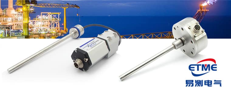
Duty features of pitch-position feedback
The hub environment can be summarised in four points: first, continuous vibration and rotation — the hub rotates with the main shaft in operation, and the sensor sees alternating load and centrifugal force; second, wide temperature — from northern winter cold to summer heat inside the nacelle, a large span, so the operating-temperature range must be checked (the distinction is in Operating Temperature vs. Storage Temperature); third, a strong electromagnetic environment — converter, generator and slip rings share one assembly, and the signal loop is easily disturbed (see EMC: Why Strong Magnetic Fields Disturb Measurement); fourth, an extremely small maintenance window — the all-in cost of one tower climb far exceeds the device itself, so reliability comes before price.
Why absolute position is a hard requirement in a pitch system
Feathering is the most basic safety action of a wind turbine. With incremental feedback, the position datum is lost after a grid drop or a control restart, the controller cannot confirm the present pitch angle, and a homing move must be executed first — which in high wind is itself an unacceptable risk. A magnetostrictive displacement sensor outputs absolute position and reads the present cylinder stroke directly after power is restored, with no reference-point switch; the principle is in Absolute vs. Incremental Position. The three blades usually each have one feedback channel; the controller compares the three readings to judge pitch consistency. On machines with a high safety requirement, a dual-channel redundant scheme can be assessed (What Is Redundant Output? The Story Behind Dual-Channel Safety Design, Series 16R redundant in-cylinder).
Comparison of pitch, yaw and hydraulic-station measuring points
| Measuring point | Function | Stroke magnitude | Key requirement | Recommended form |
|---|---|---|---|---|
| Pitch cylinder (one per blade) | Pitch-angle control and feathering confirmation | Short to medium stroke | Absolute position, vibration resistance, wide temperature | In-cylinder |
| Yaw hydraulic brake cylinder | Brake clamp-stroke confirmation | Short stroke | Reliable in-position criterion | In-cylinder or external |
| Hydraulic-station accumulator / oil level | Stored energy and oil-quantity monitoring | Short to medium stroke | Long-term stability, low maintenance | External / position type |
| Tower lift / maintenance mechanism | Position confirmation | Long stroke | Protection class, long range | External |
Mounting form and protection choice
Pitch cylinders mostly use in-cylinder mounting: the rod is in a deep piston-rod bore (minimum bore generally ≥12.7 mm), pressure rating is chosen on system pressure (by series: Series 16/16R is 350 bar working / 530 bar peak, Series 17/17EX is 350/600 bar, Series 19 in-cylinder is 300/600 bar), the rod is not exposed to oil mist and condensate in the hub, and vibration behaviour is better than an external-bracket scheme. Offshore machines or salt-spray environments need extra attention to weather resistance of connectors and cable jackets; focus on connector and cable-jacket weathering offshore and target IP67 upward (meaning in IP65/67/68/69K Is Not a Numbers Game). If the hydraulic station is in a special location that may have flammable gas (for example an offshore-platform ancillary), select to explosion-protection requirements; intrinsically safe types include Series 17EX intrinsically safe. In-cylinder needs of standard machines are in Series 16 cylinder-integrated. The general hydraulic closed-loop framework is in Why Choose Magnetostrictive Sensing for Hydraulic Cylinder Position Control.
Signal interface and remote monitoring
Communication between the hub controller and the nacelle is mostly through slip rings, so the interface should minimise interference and voltage drop of analog over a long run. CANopen (DSP406 profile) is fairly common in wind-pitch systems: several position nodes can hang on one bus and carry diagnostic information. Configuration points are in How to Connect Magnetostrictive Displacement Sensors to a Fieldbus; fieldbus products include Series 194 CANopen. Position data can also be sent to SCADA for pitch-mechanism degradation-trend analysis — a gradually lengthening pitch response time in the same wind-speed band often appears before a fault alarm.
Practical tips for engineers
- For in-cylinder mounting, piston-rod bore lower limit is ≥12.7 mm (Ø10 rod). Series 17 also has a Ø13 mm through-hole + M18×1.5 on the cylinder cap; Series 16 uses Ø18G7. Do not mix pressure ratings: Series 16/16R is 350 bar working / 530 bar peak, Series 17/17EX is 350/600 bar, Series 19 in-cylinder is 300/600 bar.
- The sensor rod should be protected against wear inside the cylinder.
- Series 19 in-cylinder types are rated 300 bar with a 600 bar peak; use these figures for selection and pressure testing.
Frequently Asked Questions
Q: Why does wind-turbine pitch use displacement feedback?
Pitch angle determines power and load, and hydraulic-cylinder position reflects pitch angle directly. Displacement feedback is used for the angle closed loop and for lock-cylinder safety confirmation.
Q: Can an intrinsically safe type be used inside a turbine?
If potentially flammable gas is present in the nacelle, Series 17EX intrinsically safe can be deployed; a safety barrier is required and cable distributed parameters must be checked — see the explosion-protection installation practice.
Q: How is accuracy held through high–low temperature cycling?
Check the operating temperature over the full temperature band, keep the electronics head away from heat sources, and use a split type if necessary; thermal drift is brought within specification by material choice and compensation.
Related Products



Related Applications

Multi-Industry Application Cases for Magnetostrictive Displacement Sensors
View Details
Series 16 Hydraulic Rod Magnetostrictive Displacement Sensor Application Cases
View Details
Series 18 Profile Magnetostrictive Displacement Sensor Application Cases
View Details