
Hydraulic Lift Cylinder: Through-Bore Plunger and External Mount
Note: Germanjet supplies magnetostrictive displacement / position sensors only; descriptions of other displacement-measurement technologies below are for technical comparison.
A magnetostrictive displacement sensor on lift-type equipment follows two paths. On a hydraulic lift (including vehicle lifts and scissor platforms) car position is determined directly by plunger- or cylinder-stroke, and displacement feedback takes part in levelling control and the deceleration curve — but the cylinder form must be confirmed first: only a single-stage (direct-acting) plunger cylinder can take a magnetostrictive displacement sensor; a multi-stage telescopic plunger cylinder cannot, for the reasons given below. On a traction lift, car position is normally given by the shaft system and encoders; displacement sensors are used mainly for condition monitoring of safety-related mechanisms such as tension-device stroke, buffer compression and brake clearance. Both applications share a strong safety attribute: feedback must be valid immediately after power is restored, and long-term maintenance-free operation is required.
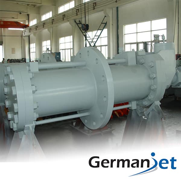
Hydraulic lifts: levelling accuracy and the deceleration curve
Levelling on a hydraulic lift depends on cylinder-stroke feedback and a floor-position look-up table. The inherent difficulty is oil-temperature influence: after continuous running the oil temperature rises, viscosity and system leakage characteristics change, and the stop position under the same control command drifts. A displacement closed loop can absorb that drift — the controller decelerates and stops on actual position, rather than estimating from time or valve opening. A 10-50 μm resolution grade is generally sufficient for levelling; repeatability (of the order of ±0.002 mm) is far better than the practical uncertainty on the mechanical side. On longer-stroke models, convert the absolute value of non-linearity at long range; the principle is given in the three accuracy terms.
A prior decision: single-stage cylinders can be used, multi-stage telescopic cylinders cannot
Hydraulic-lift plunger cylinders come in two constructions. They must be distinguished before selection, otherwise the scheme is blocked from the outset.
A single-stage (direct-acting) plunger cylinder has one plunger and one barrel, with a through cavity over the full stroke. The magnetostrictive rod can be inserted from a deep bore in the cylinder base, with the magnet fixed on the plunger end face. This is a standard in-cylinder scheme, and is the subject of this article.
A multi-stage (telescopic) plunger cylinder has two or more barrels nested and extending in stages. Internally there is no through cavity spanning the full stroke for a measuring rod to pass through, and the pistons sit in barrels of different diameters, so they cannot share a single waveguide — whether with one magnet or several, a magnetostrictive displacement sensor cannot be installed. Low-rise hydraulic lifts often use two- or three-stage telescopic cylinders to reduce pit depth. On such machines, a multi-stage telescopic plunger has no through bore for one magnet ring, so mount externally along the guide rail instead with an externally mounted displacement sensor, or measure the last-stage stroke only. The applicable bounds of multi-magnet measurement and the alternatives are detailed in multi-magnet measurement: several positions from one waveguide.
Displacement monitoring of safety-related mechanisms
Several mechanisms on a traction lift are suitable for added displacement monitoring: tension-device stroke on the ropes (reflecting rope elongation and wear trend), buffer compression (post-incident assessment), brake-shoe clearance (wear monitoring), and door-mechanism stroke. The value of these measuring points is not real-time control but trend data: a month-by-month unidirectional change in tension-device stroke usually appears before a rope-degradation alarm. If a safety-related loop requires dual channels, a redundant scheme should be assessed (see redundant output and dual-channel safety design and Series 16R redundant in-cylinder).
Measuring points and schemes
| Measuring point | Purpose | Recommended form | Resolution grade | Key requirement |
|---|---|---|---|---|
| Hydraulic-lift plunger cylinder (single-stage direct-acting only) | Levelling and deceleration control | In-cylinder or profile type | 10-50 μm | Absolute position, long stroke |
| Scissor / lift-platform cylinder | Height control and limits | In-cylinder | 20-50 μm | Vibration resistance, IP67 or better |
| Tension-device stroke | Rope-elongation trend monitoring | Profile type | 50-100 μm | Long-term stability, maintenance-free |
| Brake clearance | Wear monitoring | Short-stroke profile | 1-10 μm | Ability to resolve small displacements |
Shaft environment and installation constraints
Shaft space is tight, humidity is high, oil and dust are common, and inspection work is done on the car top or in the pit. Three installation lessons apply. First, fix the rod along the guide-rail direction, avoid interference with the car motion path, and leave allowance at both ends of the full stroke to stay clear of the dead zones (see effective range and measuring dead zones). Second, the travelling portion of the cable must use travelling cable or an energy chain; a hanging span is a high-incidence point for core breakage. Third, take a protection rating of IP67 or better; where the pit may collect water, consider a higher rating (see IP protection ratings). Products to consider include Series 13 mobile hydraulic (25 g vibration / 100 g shock) and Series 16 in-cylinder. General points for a hydraulic closed loop are given in why hydraulic cylinder position control uses magnetostrictive sensing.
Analogy with other long-stroke hydraulic scenes
Hydraulic lifts and water-conservancy hoists are highly similar in “long stroke, absolute position, little maintenance”; compare water gates and hoists and hydraulic cylinder stroke monitoring in water pumping stations. The difference is that lifts demand a higher safety integrity and denser motion, so they place stricter requirements on continuous availability and diagnostic capability of the feedback. Fieldbus types can carry diagnostic status; wiring notes are in the practical fieldbus guide.
Practical tips for engineers
- For in-cylinder mounting, piston-rod bore lower limit is ≥12.7 mm (Ø10 rod). Series 17 also has a Ø13 mm through-hole + M18×1.5 on the cylinder cap; Series 16 uses Ø18G7. Do not mix pressure ratings: Series 16/16R is 350 bar working / 530 bar peak, Series 17/17EX is 350/600 bar, Series 19 in-cylinder is 300/600 bar.
- The sensor rod inside the cylinder should be protected against wear.
- Series 19 in-cylinder types are rated 300 bar, 600 bar peak; use these figures for selection and pressure testing.
Frequently Asked Questions
Q: How is hydraulic-lift cylinder displacement measured?
Piston position in the cylinder reflects car height directly. An in-cylinder or profile-type magnetostrictive sensor reads absolute position and can be used as the levelling and limit criterion.
Q: Is car position lost after a power failure?
No. Absolute position is read on power-up, which helps locate the car for trapped-passenger rescue and recovery, without floor-by-floor homing.
Q: Do lift sensors need to be maintenance-free?
Yes. The shaft maintenance window is limited. Non-contact, no wear and no homing significantly reduce maintenance cost.
Related Products



Related Applications

Multi-Industry Application Cases for Magnetostrictive Displacement Sensors
View Details
Series 16 Hydraulic Rod Magnetostrictive Displacement Sensor Application Cases
View Details
Series 18 Profile Magnetostrictive Displacement Sensor Application Cases
View Details