
Oil Drilling Tool Position: Choosing an Explosion-Proof Displacement Sensor by Zone
Explosive wellhead areas call for an explosion-proof magnetostrictive displacement sensor selected by hazardous-area class before measuring range. On an oil-drilling site the technical difficulty of displacement measurement is not the measurement itself, but compliant deployment in an explosive-gas atmosphere: combustible gas may be present in the wellhead area, so all electrical equipment must be selected to the corresponding explosion-protection type according to the hazardous-area classification, and the intrinsically safe parameters of the whole loop (sensor + cable + isolating / safety barrier + control side) must match. On the measuring-point side, drill-string feed (weight-on-bit) stroke, hydraulic catwalks, iron-roughneck clamp and torque cylinders, blowout-preventer ram position, and monkey-board mechanisms on the derrick all need reliable absolute-position feedback from a magnetostrictive displacement sensor.
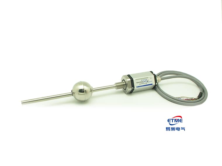
Hazardous-area classification and choice of explosion-protection type
Hazardous areas are classified Zone 0 / Zone 1 / Zone 2 by the frequency and duration of combustible gas. Corresponding common explosion-protection types are: intrinsically safe Ex ia (usable in Zone 0), Ex ib (Zone 1), flameproof Ex d (Zone 1/2), and dust-protected Ex tD (combustible-dust atmospheres). The intrinsically safe type avoids ignition in principle by limiting loop energy, and is suited to low-power equipment such as a magnetostrictive displacement sensor; the flameproof type relies on an enclosure that withstands an internal explosion and prevents flame transmission. Basic concepts and selection criteria are given in explosion-protection basics: intrinsic safety, flameproof and dust protection. For intrinsically safe products see Series 17EX intrinsically safe.
Explosion-protection types compared
| Explosion-protection type | Applicable zone | Protection principle | Loop requirement | Typical deployment |
|---|---|---|---|---|
| Ex ia (intrinsically safe) | Zone 0/1/2 | Limit loop energy | Safety barrier required; parameters must match | Instrumentation near the wellhead |
| Ex ib (intrinsically safe) | Zone 1/2 | Limit loop energy | Safety barrier required | Ordinary hazardous areas |
| Ex d (flameproof) | Zone 1/2 | Flameproof enclosure | Strict sealing and fastening of the terminal chamber | Higher-power equipment |
| Ex tD (dust) | Dust atmospheres | Enclosure temperature limit and dust exclusion | Surface-temperature limitation | Solids-control / storage and transfer |
Intrinsically safe circuits are physically segregated, usually marked in blue, and earthed to code; barrier Uo/Io/Po must not exceed sensor Ui/Ii/Pi and cable Co/Lo.
Deployment points for an intrinsically safe loop
Intrinsic safety is not completed by “buying one intrinsically safe sensor”; it is an attribute of the whole loop. At deployment, four groups of parameters must be matched: the barrier output parameters (Uo, Io, Po) must not exceed the sensor’s allowed input parameters (Ui, Ii, Pi); the cable’s distributed capacitance and inductance must be included in the loop totals and must not exceed the allowed values (Co, Lo). In addition, intrinsically safe wiring must be physically segregated from non-intrinsically safe circuits (separate trunking and terminal strips, usually identified in blue), and earthing must follow the code. These details go wrong more easily than the sensor model itself. The selection and deployment framework can be compared with explosion-protected area selection: which certification applies to Zone 0/1/2 and installing in hazardous areas: intrinsically safe wiring and isolating barriers.
Drilling measuring points and duty
Mechanical duty on a drilling site is equally severe: drilling-fluid (mud) splash, salt mist and sulphides, severe vibration, wide temperature, and, on offshore platforms, high humidity and salt mist. Displacement measuring points should preferably be in-cylinder so that the rod is not exposed; a profile type must have a guard. Long-stroke mechanisms (for example monkey-board pipe handling and catwalk transfer) can consider a flexible long-stroke scheme (Series 19F flexible long-stroke). The general selection framework for hydraulic circuits is given in why hydraulic cylinder position control uses magnetostrictive sensing. A protection rating of IP67 or better is recommended; see IP protection ratings. Explosion-protected deployment experience from chemical plants can be compared with intrinsically safe position monitoring for chemical-reactor agitator travel.
Signals and centralised monitoring
The driller’s cabin needs a centralised display of each mechanism’s position. An intrinsically safe loop commonly uses 4-20 mA via a safety barrier — simple and reliable. If a fieldbus is used, the applicability and certification scope of that fieldbus type in an explosion-protected loop must be confirmed; an ordinary industrial scheme must not be assumed. General points on wiring and termination are in the practical fieldbus guide.
Frequently Asked Questions
Q: Can ordinary sensors be used on a drilling site?
No. A combustible-gas atmosphere requires intrinsic safety or flameproof protection. Series 17EX intrinsically safe types can be used in Zone 0/1 and must be paired with a safety barrier.
Q: How is a safety barrier matched to an intrinsically safe loop?
Match barrier Uo/Io/Po to sensor Ui/Ii/Pi, and account for cable distributed capacitance and inductance; see the article on explosion-protected installation.
Q: What about vibration and salt mist on an offshore platform?
Specify 25 g vibration resistance and IP69K protection, with connectors facing down. Intrinsically safe models still require compliant wiring.
Related Products
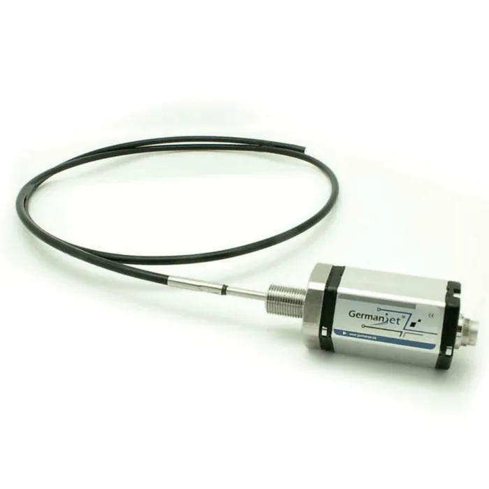
Series 19F Flexible Long-stroke
View Product
Series 17 Hydraulic Cylinder Integrated
View Product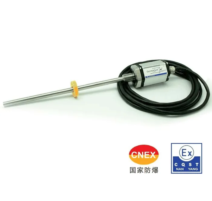
Series 17EX Intrinsically Safe Explosion-proof
View Product
Series 18 External
View ProductRelated Applications

Multi-Industry Application Cases for Magnetostrictive Displacement Sensors
View Details
Series 17 Hydraulic Cylinder Integrated Magnetostrictive Displacement Sensor Application Cases
View Details
Series 18 Profile Magnetostrictive Displacement Sensor Application Cases
View Details