17EX Intrinsic Safety Explained: Deploying Displacement Sensors in Flammable Gas Atmospheres
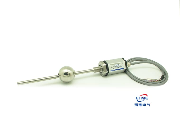
17EX is the intrinsically safe (Ex ia / ib) explosion-protected version of Germanjet Series 17 magnetostrictive displacement sensor, for hazardous areas where flammable gas or vapour may be present. The explosion-protection mechanism of intrinsic safety is to limit loop energy — voltage, current, inductance and capacitance are held at a level that cannot ignite an explosive mixture even on short-circuit or open-circuit. It does not “contain” an explosion in an enclosure; it does not produce enough ignition energy in the first place. That determines how 17EX is deployed: the sensor body, cable and safety barrier must be designed as one loop; none can be omitted. Measuring performance matches standard Series 17, and mounting is the same hydraulic-cylinder integrated form.
Where intrinsic safety, flameproof and dust explosion protection apply
| Protection type | Marking | Mechanism | Usable area | Field deployment |
|---|---|---|---|---|
| Intrinsic safety | Ex ia / Ex ib | Limits loop energy; no ignition source is produced | ia may be used in Zone 0; ib may be used in Zone 1 | Must be used with a safety barrier/isolator; loop parameters must match |
| Flameproof | Ex d | Enclosure withstands an internal explosion and prevents flame transmission | Zone 1 / Zone 2 | Heavy enclosure; the terminal chamber must be sealed to the rules |
| Dust explosion protection | Ex tD | Enclosure limits dust ingress and surface temperature | Combustible-dust atmospheres | Watch surface temperature and dust build-up |
17EX is an intrinsically safe type. The first selection step is not to look at the product, but to confirm the site area classification (Zone 0 / 1 / 2) and the gas group and temperature class, then work back to the usable protection type. The principle differences of the three types are in Explosion-protection basics: intrinsic safety, flameproof and dust explosion protection distinguished; the mapping of areas to certification is in Selecting for hazardous areas: which certification for Zone 0/1/2.
The three parts of an intrinsically safe loop
Many sites treat “we bought an explosion-protected sensor” as “explosion protection is done”. That is the most common compliance gap. A complete intrinsically safe loop has three parts; if any one is non-compliant, the whole loop is not intrinsically safe:
- Field instrument (17EX body): provides the intrinsically safe parameters Ui / Ii / Pi / Ci / Li;
- Associated apparatus (safety barrier or isolator): located in the safe area, provides output parameters Uo / Io / Po / Co / Lo, and is responsible for energy limiting;
- Connecting cable: its distributed capacitance and inductance count in the loop total; length is not chosen at will.
The matching rule is item-by-item: Uo ≤ Ui, Io ≤ Ii, Po ≤ Pi, and Co ≥ Ci + cable capacitance, Lo ≥ Li + cable inductance. If any one is not met, the loop loses its intrinsically safe character. This check must be completed and filed at the design stage. Wiring detail is in Installing in hazardous areas: intrinsically safe wiring and isolation barriers.
Deployment steps in a flammable-gas atmosphere
Step 1: confirm the area classification. The user’s safety or process department supplies the hazardous-area drawing, stating whether the mounting point is Zone 0, Zone 1 or Zone 2, and the gas group and temperature class. The sensor’s Ex marking must cover that area requirement.
Step 2: check intrinsically safe parameters and select the barrier. Match parameters by the rule above. Zener barriers require a reliable intrinsically safe earth; galvanic isolators do not need an intrinsically safe earth but cost slightly more — most sites choose isolators because earthing conditions are imperfect.
Step 3: separate the wiring. Intrinsically safe loop cables must be physically separated from non-intrinsically safe circuits: separate trunking, separate terminals, specified spacing between terminals, and blue identification. Sharing a trunk lets energy from a non-intrinsically safe circuit couple into the intrinsically safe loop.
Step 4: earthing and equipotential bonding. Intrinsically safe earthing and protective earthing must follow site rules. The shield earth must not be multi-point, forming a circulating current. General shield-earthing principles are in Shielded cable: single-end versus both-end earthing.
Step 5: documentation and acceptance. Keep the intrinsically safe loop calculation, equipment explosion-protection certificates and installation records. Inspection of explosion-protected sites often checks documents before hardware.
17EX versus standard Series 17
| Comparison | 17EX intrinsically safe | Series 17 standard |
|---|---|---|
| Usable area | Explosive-gas hazardous area (to ia / ib grade) | Non-hazardous area only |
| External accessories | Safety barrier / isolator required | Not required |
| Cable length | Limited by loop capacitance and inductance | Consider signal and voltage drop only |
| Wiring requirement | Physical separation of IS and non-IS circuits | Ordinary industrial wiring |
| Mounting form | Hydraulic-cylinder integrated; piston-rod bore ≥12.7 mm, cap M18×1.5 | As left |
| Pressure rating | 350 / 600 bar | 350 / 600 bar |
| Measuring performance | Resolution 1–100 μm, repeatability of the order of ±0.002 mm | As left |
| Output interface | Constrained by IS energy limiting; analog is common | Analog / SSI / fieldbus optional |
Note the last row: energy limiting of an intrinsically safe loop constrains usable output forms and communications. When designing a fieldbus architecture, confirm in advance that the chosen protocol is feasible under intrinsically safe conditions; do not assume that a non-explosion-protected interface scheme can be copied. The integration characteristics of standard Series 17 are in Series 17 explained.
Typical applications
17EX is commonly used in oil drilling and production, chemical reaction plant, oil and gas storage and transfer, and paint and solvent shops. What these sites share is a hydraulic actuator that needs a position closed loop, together with flammable gas or vapour. Industry applications are covered in Drill-string displacement and explosion-protected deployment in oil drilling and Agitator and position monitoring in chemical reactors, explosion-protected. For export equipment, also check the destination market’s certification requirements; see Selecting for export equipment: how to read CE / ATEX / UL.
Product pages and neighbouring options: 17EX intrinsically safe type, Series 17 standard type, Series 16 cylinder-integrated; horizontal selection across the cylinder-integrated range is in Comparing the whole cylinder-integrated range.
Frequently Asked Questions
Q: What is the difference between intrinsically safe and flameproof explosion-protected displacement sensors?
Intrinsically safe Ex ia/ib limits loop energy so that an explosive mixture cannot be ignited; ia may be used in Zone 0 and ib in Zone 1, and a safety barrier or isolator is required. Flameproof Ex d relies on the enclosure to withstand an internal explosion and prevent flame transmission, and suits Zone 1/2. Dust explosion protection Ex tD relies on the enclosure to limit dust ingress and surface temperature. 17EX is an intrinsically safe type.
Q: Does buying an intrinsically safe sensor make the loop intrinsically safe?
No. A complete intrinsically safe loop comprises the field instrument, the safety barrier or isolator, and the connecting cable. Uo ≤ Ui, Io ≤ Ii, Po ≤ Pi must be checked item by item, and Co ≥ Ci plus cable capacitance, Lo ≥ Li plus cable inductance. If any item is not met, the whole loop is not intrinsically safe.
Q: Can the cable of an intrinsically safe loop be lengthened at will?
No. The cable’s distributed capacitance and inductance count in the loop total; length is constrained by the remaining Co and Lo margin. For long-distance transmission the cable parameters must be included in the intrinsically safe check at the design stage; the cable must not be extended at will on site.
Q: Are the installation requirements of 17EX the same as standard Series 17?
Mechanical installation is the same — both are hydraulic-cylinder integrated, with a ≥12.7 mm piston-rod bore, pressure rating by series: Series 16/16R is 350 bar working / 530 bar peak, Series 17/17EX is 350/600 bar, Series 19 in-cylinder is 300/600 bar, and the same measuring performance. The difference is electrical: 17EX must be used with a safety barrier, IS and non-IS circuits must be physically separated, and usable output forms are constrained by energy limiting.
Related Products

Series 17 Hydraulic Cylinder Integrated
View Product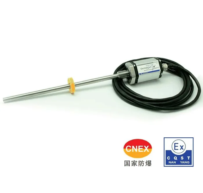
Series 17EX Intrinsically Safe Explosion-proof
View Product
Series 16 Hydraulic Cylinder Built-in
View Product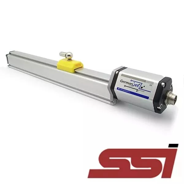
Series 19 SSI Digital Interface
View ProductRelated Applications

Multi-Industry Application Cases for Magnetostrictive Displacement Sensors
View Details
Series 16 Hydraulic Rod Magnetostrictive Displacement Sensor Application Cases
View Details
Series 17 Hydraulic Cylinder Integrated Magnetostrictive Displacement Sensor Application Cases
View Details