
Extrusion Press Main Cylinder: Speed, Butt and Long Stroke
If the position feedback on an extrusion press is treated as nothing more than an end stop, it will be specified wrong. The same reading serves three jobs at once: closing the ram speed loop, switching from rapid approach to pressing, and calculating how much butt is left. Those three want different resolution, refresh and mounting, so decide the priority first.

Four Points Worth Instrumenting
- Main cylinder stroke (stem position). The highest value point. Ram speed, butt length and return limit all come from here.
- Container-to-die closure.A proximity switch tells you it arrived; it cannot tell you how hard it is pressing.
- Butt shear position. You need to know how much scrap is left before the shear comes down.
- Runout table and puller.Long travel, low accuracy. A draw-wire or encoder is enough — no reason to spend magnetostrictive money here.
Only the first two justify the cost. The test is simple: continuous value, closed loop, or position known after a power cut — then use a magnetostrictive displacement sensor. Arrival signal only — a proximity switch is cheaper.
Why Ram Speed Has to Be Closed Loop
Ram speed sets the exit temperature of the profile, and exit temperature decides quench behaviour and surface quality. If speed drifts, the head and tail of the same profile end up with different structure and dimensions. The input to that speed loop is the derivative of cylinder position, so refresh rate and resolution of the position value decide whether the loop can be stable at all.
There is a trap here: differentiating a slow pressing move amplifies noise. A position jitter of 0.05 mm over a one-second cycle is a fake 0.05 mm/s, while the real ram speed is only a few mm/s — the artefact is a large fraction of the signal. Filter or differentiate on the controller side; do not expect the position value to smooth itself. On matching refresh to cycle time, see response time and refresh rate.
Two Geometry Problems of Long Stroke
Main cylinder strokes run from a few hundred millimetres to well over two metres, depending on tonnage and machine design. Once the stroke gets long, the first problem is geometry, not electrics.
- A horizontally mounted probe sags.Supported at both ends and empty in the middle, the middle must bend. What fails first is not accuracy but the clearance between magnet and probe: one side bottoms out, the other opens up, and wear plus occasional dropouts follow. See horizontal mounting and probe sag.
- Dead zones shrink as a ratio but still have to be deducted.On a long stroke the dead zone is a smaller share and gets ignored; when the mechanical zero lands inside it, the symptom is "no reading at the end of stroke". Deduct per the model's installation drawing, not by rule of thumb — see effective stroke and dead zone.
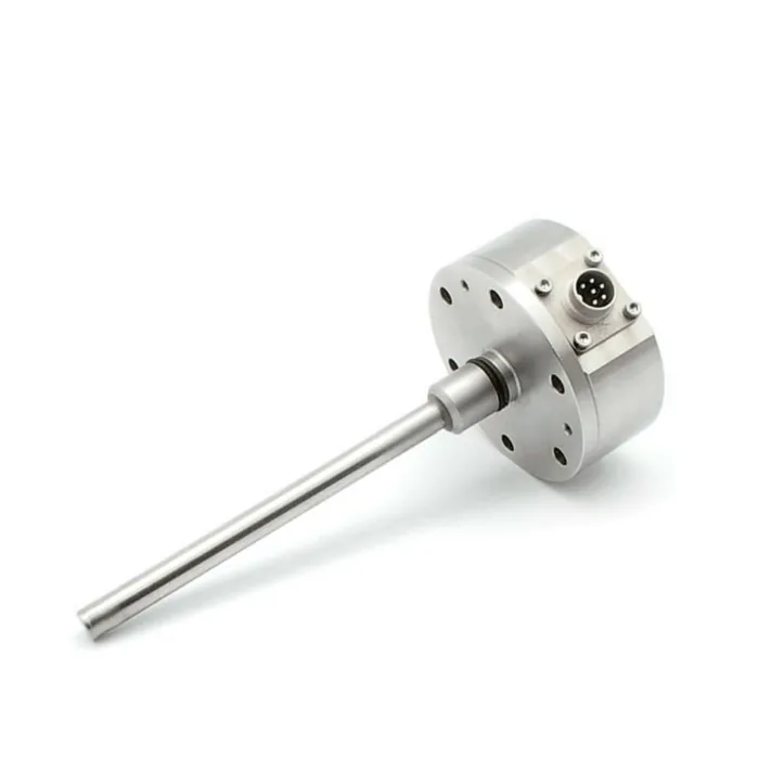
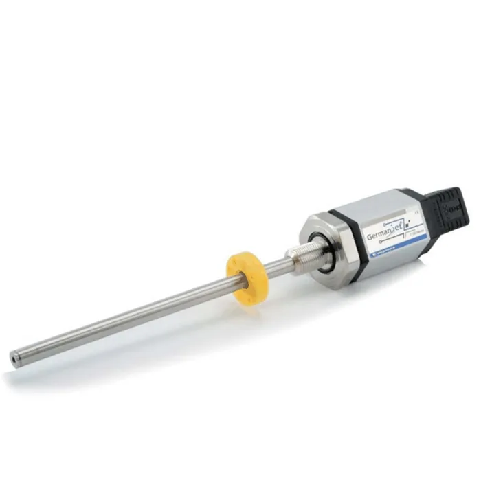
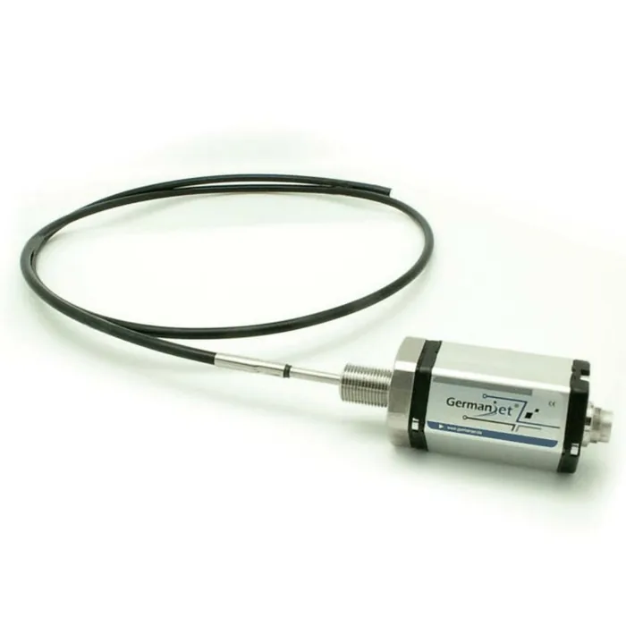
The cleaner answer is to put the sensor inside the cylinder so probe and piston rod are coaxial, which makes the geometry problem disappear. Both Series 16 in-cylinder and Series 17 cylinder-integrated follow that route; where the stroke is very long and the barrel cannot be bored, Series 19F flexible uses a bendable probe routed along the machine.
Heat Means Radiation and Conduction, Not Air Temperature
The container and die area runs at several hundred degrees, but the electronics head never sits in that. Two things have to be handled: radiant heat from the die and butt area, and conducted heat coming in through the barrel and the probe flange. A shop floor at 50 °C air temperature can still leave a flange too hot to hold.
- Mount the head at the end away from the die, put a heat shield between, and never strap it to the container wall.
- Hydraulic oil temperature is stable, and bulk temperature rise is covered by selection; local radiant heat is a structure and shielding problem.
- Long-term heat ages seals first; once moisture or oil gets in, the symptom is drift rather than failure. See reading IP65 through IP69K.
Choosing the Output
The three jobs want different things: the speed loop wants fast refresh, butt length only wants resolution, and the return limit only wants a switch. Common practice is analogue for the speed loop and a bus for diagnostics, or all-bus so position and status come back together.
- Analogue (0-10 V / 4-20 mA).Simple wiring, low latency, good for single-machine retrofits — Series 19 analogue.
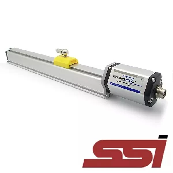
- SSI.Absolute, strong against interference, suited to long cable runs and electrical noise, but it occupies a clock channel — Series 19 SSI.
- CANopen / EtherCAT / PROFINET.Several axes on one cable with diagnostics available, at the cost of configuration time — CANopen, EtherCAT, PROFINET.
Do not scatter protocols across one workshop; follow the existing backbone, see choosing a bus from the PLC hardware.
Three Things Easily Missed on Site
- Graphite dust gets into connectors.Graphite lubricant is standard in extrusion, and conductive dust inside a connector causes intermittent shorts. Point connectors down and fit dust caps; cheaper than cleaning pins later.
- Butt shear shock reaches the sensor.The impact travels through the frame, and with weak clamping the reading jumps once — the sensor is not faulty. On mounting stiffness, see a thin mounting plate transmits vibration like a tuning fork.
- Do not use one filter for the rapid return.The return runs an order of magnitude faster than pressing, and a filter tuned for pressing will clip the peak and delay the limit. Set the two segments separately.
Walk stroke, mounting, output, accuracy and environment before fixing a part number — see five-step selection; deducting dead zones from stroke is covered in stroke calculation in practice. Long-stroke machines share thinking with rolling mill gauge control, see long-stroke solution for roll gap control.
Frequently Asked Questions
Q: Why not use a draw-wire sensor on an extrusion press main cylinder?
Dust and vibration. Graphite-bearing dust wears and jams the cable, and frame shock makes the wire oscillate into fake displacement. The longer the stroke the worse it gets, so in-cylinder or flexible-probe designs are usual.
Q: How fast does the speed loop need the position value?
Look at the loop bandwidth, not the stroke. Pressing is only a few mm/s, but the loop must stay stable under disturbance, so refresh must be clearly shorter than the loop integral time, with controller-side filtering for quantisation noise.
Q: How far should the electronics head stay from the die?
There is no universal number; it depends on radiant intensity and shielding. Mount it at the far end, put a heat shield between, and keep it off the container wall. Heat ages seals first, showing as drift.
Q: What resolution does butt length control need?
Less than the speed loop. Butt is a matter of millimetres to tens of millimetres, so 0.05 mm resolution is plenty; repeatability and zero stability matter more than the headline number.
Related Products
Related Applications
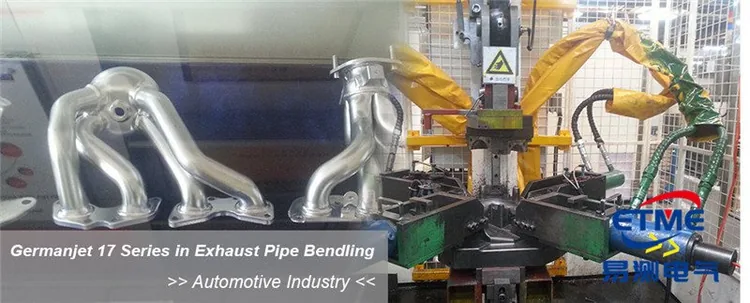
Series 16 Hydraulic Rod Magnetostrictive Displacement Sensor Application Cases
View Details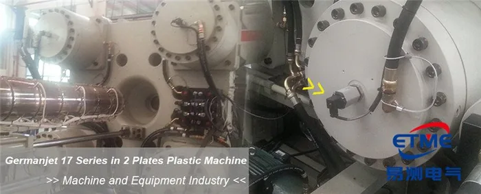
Series 17 Hydraulic Cylinder Integrated Magnetostrictive Displacement Sensor Application Cases
View Details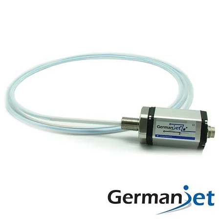
Series 19F Flexible Process Displacement Sensor Application Cases
View DetailsWhatever the question above, it comes back to the same device.magnetostrictive displacement sensorThe product range lists every series by stroke, mounting style and output interface, which is the quickest way into a selection.
← Back to News