Technical Q&A

Frequently asked questions and technical answers on magnetostrictive displacement sensors

All Categories

Articles in "Technical Q&A"

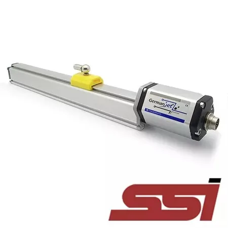
SSI jumps after a longer cable: drop the clock to match the length

SSI jumps after a longer cable: drop the clock to match the length

162 and 192 share one table: longer cable, lower maximum rate; minimum clock spacing 48 μs. Occasional huge numbers — drop the clock first. Patterned jumps — check Gray versus binary.

Analogue reading at zero: end of stroke, or a broken wire?

Analogue reading at zero: end of stroke, or a broken wire?

On 4-20 mA the start of stroke is still about 4 mA; a broken loop falls near 0. On 0-10 V, 0 V cannot tell zero from an open cable. Check the lamp, then measure at the sensor — do not swap the rod first.

Why Do Magnetostrictive Displacement Sensor Prices Vary So Much? Six Factors Behind the Quote

Why Do Magnetostrictive Displacement Sensor Prices Vary So Much? Six Factors Behind the Quote

Two magnetostrictive displacement sensors can differ in price by several times. This article breaks down the six core factors: stroke, accuracy, output interface, protection, certification and brand.

Checking a Magnetostrictive Displacement Sensor with a Multimeter: 5 Steps to Locate the Fault

Checking a Magnetostrictive Displacement Sensor with a Multimeter: 5 Steps to Locate the Fault

Without dismantling the machine or returning the unit, use a multimeter in five steps to judge whether a magnetostrictive displacement sensor is good: check supply, output, insulation and the magnet, and decide whether the fault is in the body or the installation.

On-Site EMC Remediation Reviewed: Handling Interference from Drives, Solenoid Valves and Welding

On-Site EMC Remediation Reviewed: Handling Interference from Drives, Solenoid Valves and Welding

Locate the problem through the three elements of source, coupling path and sensitive device, then review the remediation and verification of three typical site situations.

Spare Parts Replacement: A Three-Layer Interchangeability Check of Mechanical, Electrical and Parameter Interfaces

Spare Parts Replacement: A Three-Layer Interchangeability Check of Mechanical, Electrical and Parameter Interfaces

Interchangeability has to hold at three levels — mechanical, electrical and parameter — and a mismatch at any one means it either won't fit or won't work.

Acceptance Testing: Five Checks on Arrival and a Three-Point Round-Trip Test After Installation

Acceptance Testing: Five Checks on Arrival and a Three-Point Round-Trip Test After Installation

Acceptance on arrival checks correctness and transport damage; acceptance after installation uses a three-point round trip to measure deviation and the forward/reverse difference, plus an interference test.

Installing in Vibrating Environments: 25 g Resistance Is a Property of the Body — Anti-Loosening Comes Down to Workmanship

Installing in Vibrating Environments: 25 g Resistance Is a Property of the Body — Anti-Loosening Comes Down to Workmanship

Separate real vibration displacement from measurement anomalies, then deal with it through three layers of anti-loosening, cable fatigue protection and the right damping approach.

Selecting Waterproof M12 Connectors and Maintaining Seals: Coding, Pin Count and Protection Class

Selecting Waterproof M12 Connectors and Maintaining Seals: Coding, Pin Count and Protection Class

The M12 is the weakest link in the chain where protection is concerned; coding match, correct tightening and seal condition are all three required — missing any one means failure.

Redundant Installation: How to Compare Two Sensors So the Comparison Actually Works

Redundant Installation: How to Compare Two Sensors So the Comparison Actually Works

The value of redundancy is that the system notices when it has measured wrongly — which requires executable comparison thresholds, delays and response logic.

Commissioning Tool: Use a Test Magnet to Separate Body Faults from Installation Problems in 5 Minutes

Commissioning Tool: Use a Test Magnet to Separate Body Faults from Installation Problems in 5 Minutes

Connect a temporary supply off-line and run the test magnet manually through the full stroke; in a few minutes you narrow the variables from the whole system down to the sensor itself.

Synchronizing Multiple Sensors: A Common Reference, a Unified Range and Time Alignment, All Together

Synchronizing Multiple Sensors: A Common Reference, a Unified Range and Time Alignment, All Together

Multi-axis synchronization accuracy depends on consistency between individual sensors, which means solving both spatial reference alignment and sampling instant alignment.

Three Causes of Fieldbus Data Loss: Termination, Address Conflicts and Water in Connectors

Three Causes of Fieldbus Data Loss: Termination, Address Conflicts and Water in Connectors

First read the master diagnostic counters to decide whether this is a communication-layer problem, then work through termination, address/baud rate and connector moisture in order.

Installing in High Temperatures: Blocking Radiation, Dissipating Heat, Split Mounting and Cable Selection

Installing in High Temperatures: Blocking Radiation, Dissipating Heat, Split Mounting and Cable Selection

Distinguish ambient temperature, media temperature and radiant heat first, then handle high-temperature duty in four steps: insulate, dissipate heat, use split mounting and select the right cable.

Installing in Hazardous Areas: The Three Elements of an Intrinsic-Safety Loop, Barrier Selection and Wiring Requirements

Installing in Hazardous Areas: The Three Elements of an Intrinsic-Safety Loop, Barrier Selection and Wiring Requirements

Intrinsic safety is a property of the whole loop, not of an individual component; certified devices, a matched safety barrier and cable distributed parameters must all be satisfied.

Long Cable Runs and Their Three Constraints: Voltage Drop, Signal Attenuation and Repeater Segmentation

Long Cable Runs and Their Three Constraints: Voltage Drop, Signal Attenuation and Repeater Segmentation

Handle voltage drop with a larger conductor cross-section or a local supply, attenuation by choosing the right signal form, and excess distance with repeater segments and local digitisation.

External Installation: Getting Bracket Rigidity, Parallelism and Carriage Float Right

External Installation: Getting Bracket Rigidity, Parallelism and Carriage Float Right

External accuracy depends on the mechanical chain formed by the bracket and carriage; the core principle is to transmit axial displacement only and impose no radial constraint.

No Output in Three Steps: Check Supply, Verify the Loop, Then Inspect the Magnet

No Output in Three Steps: Check Supply, Verify the Loop, Then Inspect the Magnet

Locate the break in three steps — supply, signal loop, magnet — with multimeter test points and pass criteria for each interface type.

Zero Calibration Step by Step: Mechanical Reference, the Two-Point Method and Controller Settings

Zero Calibration Step by Step: Mechanical Reference, the Two-Point Method and Controller Settings

From establishing the mechanical reference to writing the zero offset and span coefficient, with the calibration sequence and verification criteria for both analog and fieldbus interfaces.

Tracking Down Reading Errors: Handle Constant, Proportional, Local and Drifting Errors Separately

Tracking Down Reading Errors: Handle Constant, Proportional, Local and Drifting Errors Separately

Measure at three points to identify the error shape, then check zero offset, span coefficient, magnet position and thermal drift in order, instead of blindly adjusting parameters.

Hydraulic Oil Cleanliness and Filter Management: The Key to Long Rod Life

Hydraulic Oil Cleanliness and Filter Management: The Key to Long Rod Life

Ferromagnetic debris attracted to the magnet and hard particles scouring the rod are the two main influence paths, and the control measures sit in the hydraulic system rather than in the sensor.

Cylinder Bore Machining Requirements: 12.7 mm Minimum Bore, Depth Allowance and Concentricity Control

Cylinder Bore Machining Requirements: 12.7 mm Minimum Bore, Depth Allowance and Concentricity Control

Three hard requirements for the deep-hole machining used in cylinder-integrated installation — piston-rod bore ≥12.7 mm, depth covering the full stroke plus allowance, and controlled concentricity.

Signal Jump Troubleshooting Flow: Isolating Electrical, Mechanical and Fieldbus Causes Layer by Layer (Save This One)

Signal Jump Troubleshooting Flow: Isolating Electrical, Mechanical and Fieldbus Causes Layer by Layer (Save This One)

First classify the fault as electrical, mechanical/magnet or fieldbus according to whether the value jumps while stationary, then work through the branches for each.

Shield Grounding at One End or Both: When to Use Which, Measured Differences and Hidden Grounding Traps

Shield Grounding at One End or Both: When to Use Which, Measured Differences and Hidden Grounding Traps

Ground the shield at the cabinet end by default for analog; both ends are acceptable for fieldbus when equipotential bonding is reliable — plus how to track down a hidden second ground.

FAQ Round-Up: 20 Common Questions About Magnetostrictive Displacement Sensors, Answered

FAQ Round-Up: 20 Common Questions About Magnetostrictive Displacement Sensors, Answered

Twenty frequently asked questions grouped into six categories — principle, accuracy, selection, installation, faults and environment — each with a one-sentence answer and a pointer to the detailed article.

Five Magnet Installation Pitfalls: Coaxiality, Gap, Loosening and Magnetic Interference Taken Apart

Five Magnet Installation Pitfalls: Coaxiality, Gap, Loosening and Magnetic Interference Taken Apart

Symptoms, criteria and remedies for five defect classes: coaxiality out of tolerance, incorrect gap, reversed or substituted magnets, loose fastening and external magnetic fields.